Air spring resilient member

a resilient member and air spring technology, applied in the direction of springs, vibration dampers, gas based dampers, etc., can solve the problems that the strength of rubber materials becomes a limiting factor, and achieve the effects of reducing the risk of bursting

Inactive Publication Date: 2006-06-20
CONTITECH LUFTFEDERSYST
View PDF16 Cites 8 Cited by
  • Summary
  • Abstract
  • Description
  • Claims
  • Application Information

AI Technical Summary

Benefits of technology

[0009]The present invention is based on the task of providing an air spring flexible member having an adequate bursting pressure and a high surface life which can be manufactured simply and cost effectively.

Problems solved by technology

However, it is to be noted for ever greater spacing, that the strength of the rubber material becomes a limiting factor for the air pressure in the air spring starting at a specific spacing between the filaments.

Method used


Image

  • Air spring resilient member
  • Air spring resilient member

Examples


Embodiment Construction

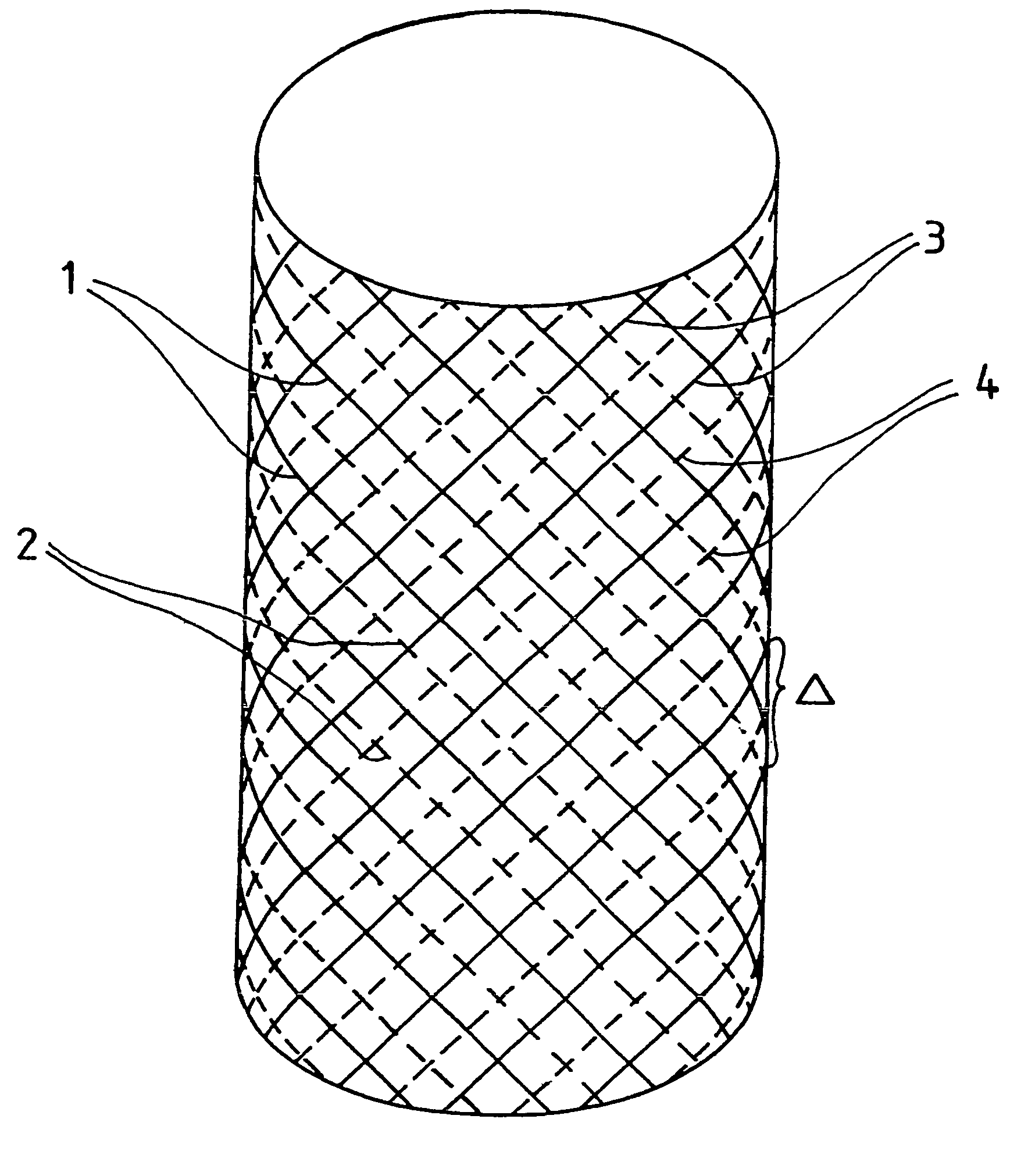
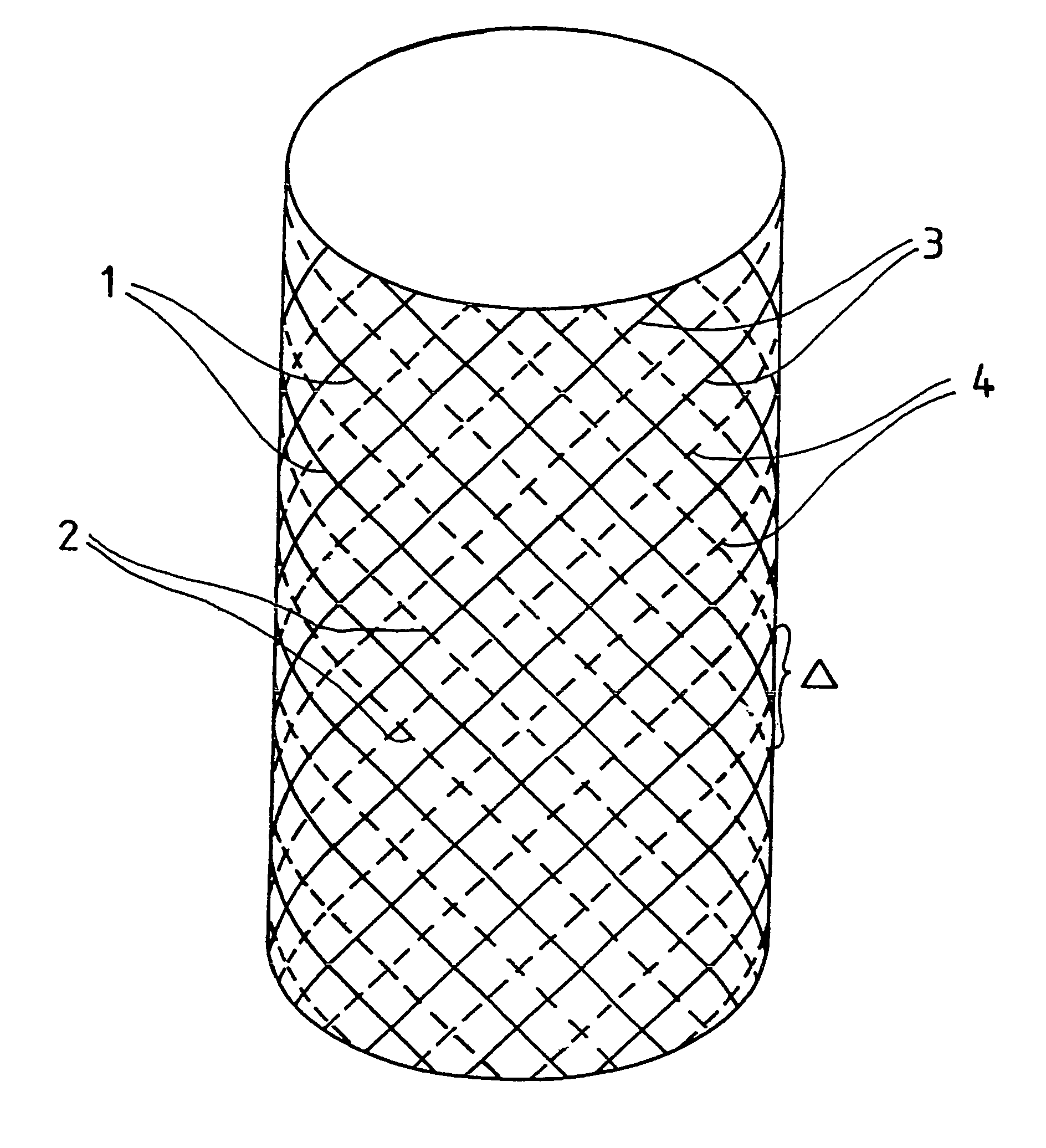
[0027]The figure shows how the reinforcing filaments 1, 2, 3, 4 run in an air spring of the invention having two mutually crossing reinforcement layers. These reinforcement filaments 1, 2, 3, 4 are completely surrounded by an elastomeric material (not shown in the figure) in the finished air spring. The filaments 1 and 2 form the inner layer and the filaments 3 and 4 form the outer layer. The filaments 1 and 3 are filaments having a higher strength, such as aramide filaments, which are arranged within a layer at a spacing Δ. Between each two aramide filaments 1, there is a filament 2 of lesser strength, for example, a filament made of polyamide or polyester and between each two aramide filaments 3 there is a filament 4 having lower strength, for example, of polyamide or polyester. In the finished product, the filaments (2, 4) reinforce the rubber material disposed between the filaments (1, 3) to a sufficient amount and prevent the point-for-point destruction (rupturing of the rubber...


PUM


Abstract

An air spring rolling-lobe flexible member is made of elastomeric material and has at least two layers of intersecting reinforcement filaments. The reinforcement filaments are arranged in an essentially parallel manner to each other at an angle between 40° and 80° to the direction of the periphery of the rolling-lobe flexible member. At least one component quantity of the reinforcement filaments (1, 2) within one layer exhibits another strength compared to the remaining component quantity thereof.

Description

FIELD OF THE INVENTION[0001]This application is the national stage of PCT / EP02 / 04398, filed Apr. 22, 2002 designating the United States.[0002]The invention relates to an air spring flexible member made of elastomeric material having at least two mutually crossing layers of reinforcement cords. The reinforcement cords are inclined at an angle of 40° to 80° to the peripheral direction of the flexible member and are arranged essentially parallel to each other within a layer.[0003]Air springs have been proved advantageous to a large extent, for example, as vehicle springs, especially for spring mounting of the wheel axles of trucks and buses. In automobiles, the use of air springs is increasing significantly because they offer a balanced comfort at high level even for vehicle bodies which are of the sporty kind.BACKGROUND OF THE INVENTION[0004]An air spring has layers of reinforcement cords which run parallel and are embedded in rubber. These reinforcement cords are also known as reinfo...

Claims


Application Information

Patent Timeline
Patent Type & Authority Patents(United States)
IPC IPC(8): F16F9/04F16J3/04
CPCF16F9/0409F16F9/04
Inventor BINDER, KLAUS
Owner CONTITECH LUFTFEDERSYST
Why Eureka
Try Eureka