
Polycrystalline ultra-hard compact constructions

a technology of polycrystalline and ultra-hard, which is applied in the direction of manufacturing tools, drilling rigs, transportation and packaging, etc., can solve the problems of difficult to form compact constructions having a substrate attached to the tsp material, difficult to form compact constructions, and high cost, so as to improve the degree of contact, reduce thermal stress, and improve the effect of attachment strength

Inactive Publication Date: 2011-03-22
SMITH INT INC
View PDF37 Cites 34 Cited by
  • Summary
  • Abstract
  • Description
  • Claims
  • Application Information

AI Technical Summary

Benefits of technology

This patent describes a new type of ultra-hard construction that is designed to improve the attachment strength between a polycrystalline ultra-hard compact and a wear and cutting device. The construction includes a support member that is attached to the compact using a braze material. The support member is made of a one-piece or unitary construction and includes sections that extend axially and radially around the compact. The support member can be made from different materials and can be designed to place the compact in a state of axial compression during the attachment process. This new construction has been found to increase the surface life of the polycrystalline ultra-hard compact and improve its attachment strength compared to conventional constructions.

Problems solved by technology

A problem known to exist with such conventional PCD compacts configured as cutting elements for use with subterranean drill bits is that the PCD compacts fracture during the process of drilling, causing the PCD compact to break away from and fall off of the drill bit body.
While such TSP materials do provide certain performance advantages, the desired lack of catalyst material makes it difficult to form a compact construction having a substrate attached to the TSP material.
The substrates for such TSP construction are conventionally attached to the TSP material by welding or brazing, which attachment has shown to be vulnerable to failure in operation.

Method used


Image

  • Polycrystalline ultra-hard compact constructions
  • Polycrystalline ultra-hard compact constructions
  • Polycrystalline ultra-hard compact constructions

Examples


Embodiment Construction

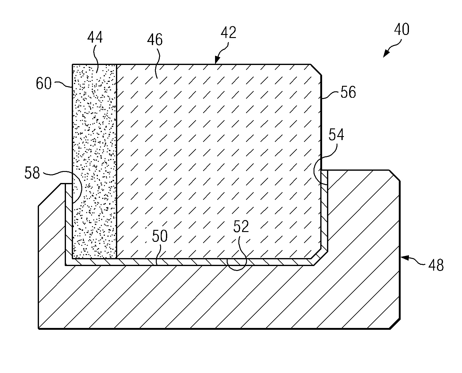
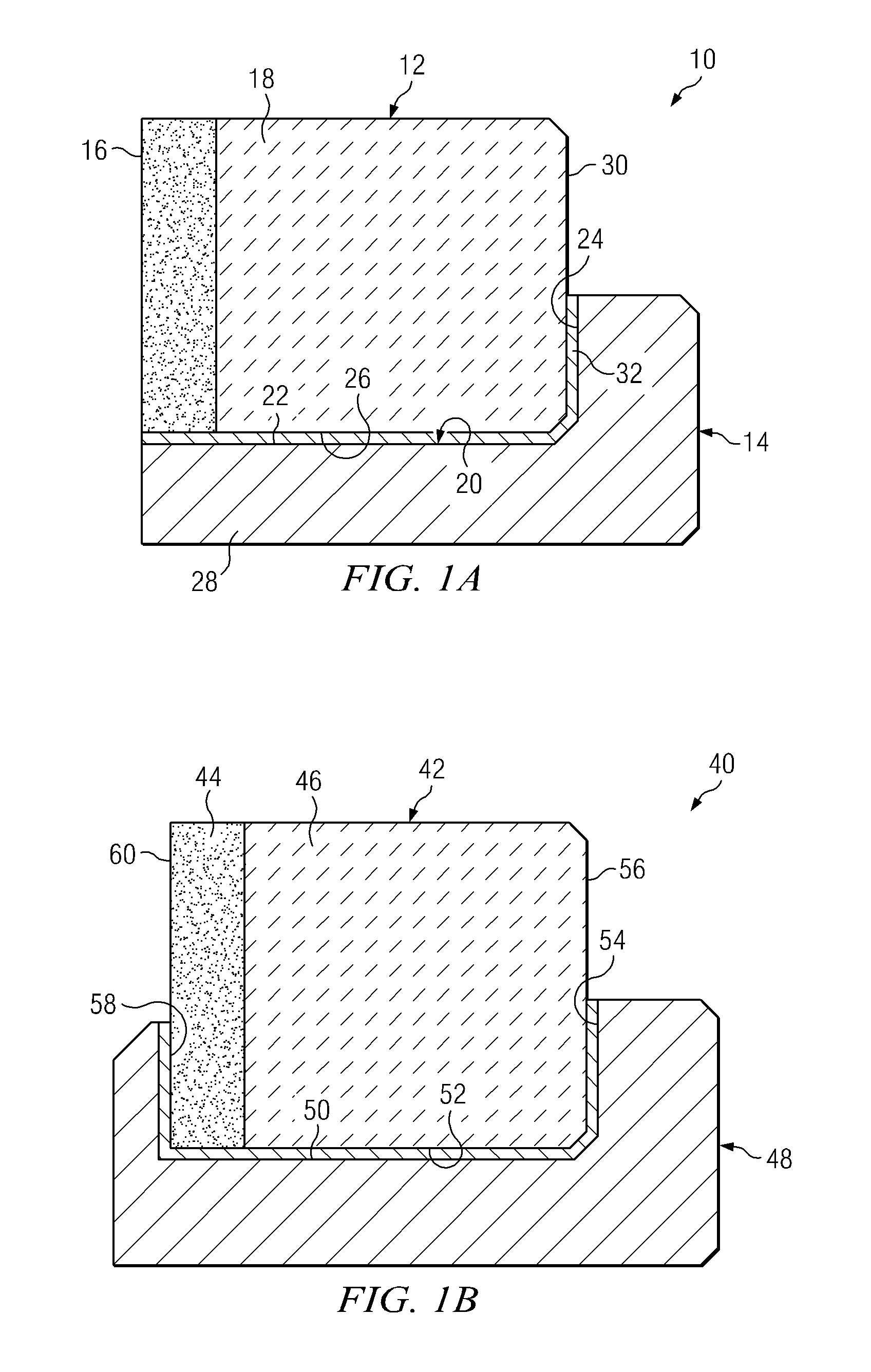
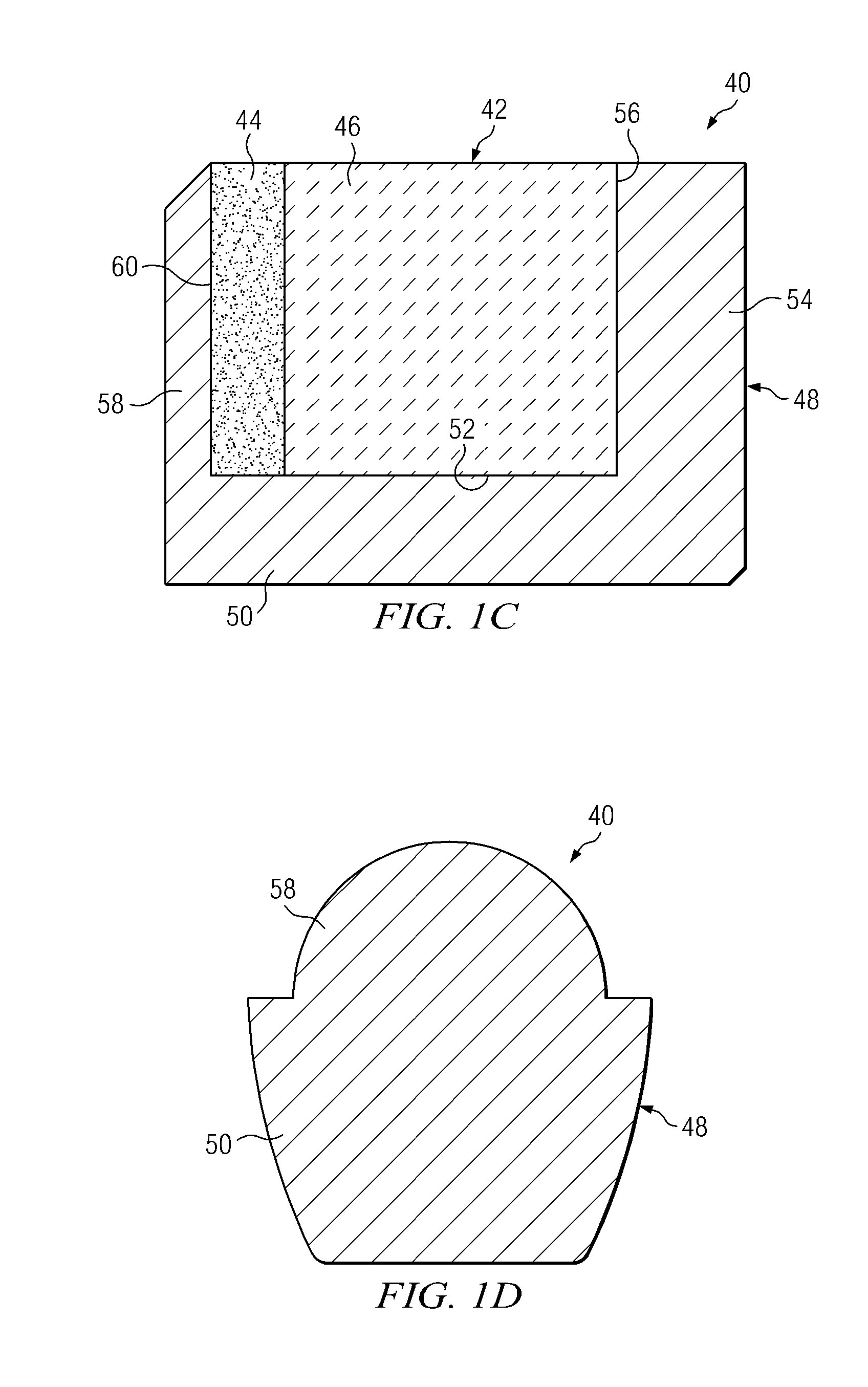
[0025]Polycrystalline ultra-hard compact construction of this invention comprise a polycrystalline ultra-hard material body that is joined to a substrate, wherein the joined together body and substrate forms a compact that is further joined to a support member. The support member is specifically engineered to provide an enhanced degree of support to the compact, and an enhanced degree of attachment between the compact and a surface of a wear and / or cutting device. The compact can be attached to the support member using one or more different types of braze materials to further enhance the strength of the construction, and / or the support member comprise two or more elements or sections made from the same or different types of materials to also enhance strength of the construction by controlling or minimizing the residual thermal stress within the construction after brazing.

[0026]Thus, polycrystalline ultra-hard compact construction constructed in accordance with principles of this inv...


PUM


Abstract

Polycrystalline ultra-hard compact constructions comprise a polycrystalline ultra-hard compact having a polycrystalline ultra-hard body attached to a substrate. A support member is attached to the compact by a braze material. The support member can have a one-piece construction including one or more support sections. The support member has a first section extending axially along a wall surface of the compact, and extending circumferentially along a portion of the compact. The support member can include a second section extending radially along a backside surface of the compact, and / or a third section extending radially along a front side surface of the compact. In one embodiment, the support member includes a second and / or third section and the compact disposed therein is in an axially compressed state. The support member is interposed between the compact and an end-use device.

Description

FIELD OF THE INVENTION[0001]This invention generally relates to polycrystalline ultra-hard compacts and, more particularly, to polycrystalline diamond compact constructions that have been specially engineered to include a support member to provide improved bond strength when attached to a desired cutting and / or wear device when compared to conventional polycrystalline compacts.BACKGROUND OF THE INVENTION[0002]Polycrystalline ultra-hard constructions, such as polycrystalline diamond (PCD) materials and PCD elements formed therefrom, are well known in the art. Conventional PCD is formed by subjecting diamond grains to processing conditions of extremely high pressure and high temperature in the presence of a suitable solvent catalyst material, wherein the solvent catalyst material promotes desired intercrystalline diamond-to-diamond bonding between the grains, thereby forming a PCD structure.[0003]The solvent catalyst material can be combined with the diamond grains prior to processing...

Claims


Application Information

Patent Timeline
Patent Type & Authority Patents(United States)
IPC IPC(8): E21B10/567
CPCE21B10/573B23K1/0008B22F7/062B22F2005/002B23K2203/00C22C2204/00B23K2201/20Y10T428/12986B23K2101/20B23K2103/52E21B10/567E21B10/46E21B10/56
Inventor VORONIN, GEORGIYMOURIK, NEPHI M.BELNAP, J. DANIEL
Owner SMITH INT INC
Learn More