Wire rope for running wire

a wire rope and running wire technology, applied in the direction of yarn, filament/thread forming, fibre treatment, etc., can solve the problems of insufficient resolution of the respective prior arts, reduced effective sectional area of the rope, wear of the rope, etc., to reduce the elongation thereof, increase the surface life, and reduce the effect of wire breakag

Active Publication Date: 2009-10-13
TOKYO ROPE MFG
View PDF11 Cites 8 Cited by
  • Summary
  • Abstract
  • Description
  • Claims
  • Application Information

AI Technical Summary

Benefits of technology

[0011]The invention has been carried out in order to resolve the above-described problems. It is an object of the present invention to provide a wire rope for a running wire capable of increasing a surface life by reducing a wire breakage at a point of contact with a core rope by constraining a movement of a wire in a rope filled with a resin member between strands and reducing an elongation thereof.
[0013]According to the invention, the core rope includes the core rope main body and the resin coating layer outwardly surrounding the core rope main body, the core rope main body and the side strand are separated from each other by the resin coating layer, and therefore, metal contact between the side strand and the core rope is prevented, and a wire breakage at a point of being contacted to the core rope can considerably be reduced. Further, by interposing the resin spacer between the strands, contact between the strands is prevented, a wire breakage at a valley of a rope between respective strands is prevented, a face pressure of a surface of the rope is reduced by increasing a portion thereof in contact with the sheave, and service life because of preventing a wire breakage at a crown of the strand in contact with the sheave by wear can considerably be prolonged. Further, the resin spacer is provided with the contour in correspondence with the outer layer wire of the side strand and extends between the outer layer wires, and therefore, the movement of the wire is constrained, an excellent effect of reducing the wire breakage at the point of contact with the core rope and of reducing an elongation of the rope is achieved.
[0015]A degree of extension of the resin between the wires is high, and therefore, the movement of the wire can stopped, because when the rope is bent by the sheave, the movement of the wire is firmly restrained, the wire breakage at the point of contact with the core rope is insignificant, and the service life is extended. Further, the elongation can be reduced.
[0016]Preferably, the resin spacer comprises a streak member formed by subjecting a thermoplastic resin selected from any of polypropylene species, polyethylene species, acrylic species, polyurethane species to extrusion molding, the streak member is provided with a sectional shape in which a head portion enlarged in a fan-like shape and a base portion in a fan-like shape smaller than the head portion are made to be continuous by a constriction edge. A thickness between the constriction edges is constituted by a value increasing a gap of arranging the side strands on layer cores by 15 through 30%, that is, when the gap of arranging the side strands is 100, the thickness is 115 through 130%.
[0018]Thereby, the movement of the wire when the rope is bent is firmly restrained, the wire breakage at the point of contact with the core rope is very insignificant, and the elongation can be reduced.

Problems solved by technology

Because of this structure, metal contact is unavoidable between the strands, and between a sheave portion and the rope thus causing wear of the rope.
Although a number of ropes have been proposed as a countermeasure thereagainst in the prior art, problems posed by the respective prior arts cannot be construed as sufficiently resolved.
However a base end portion of the spacer is formed by a wedge-like shape, the wedge portion reaches a center of the rope, and therefore, an effective sectional area of the rope is reduced so that it is difficult to use the rope for an application that involves a high breaking load.
Also, when the reinforcement core is disconnected at an early stage, there is a possibility of jumping out the reinforcement core from the filling material.
Furthermore, since the reinforcement core is provided for the filling material, a special equipment is needed for fabrication thereof at increased cost.
However, here a resin having a high strength of a biaxially oriented molecular structure or the like is used, and therefore, the spacer is difficult to be deformed and does not extend between wires constituting a side strand.
Therefore the wire can move and a wire breakage at a point of contact with a core rope cannot be restrained and elongation of the rope is increased.

Method used


Image

  • Wire rope for running wire
  • Wire rope for running wire
  • Wire rope for running wire

Examples


examples

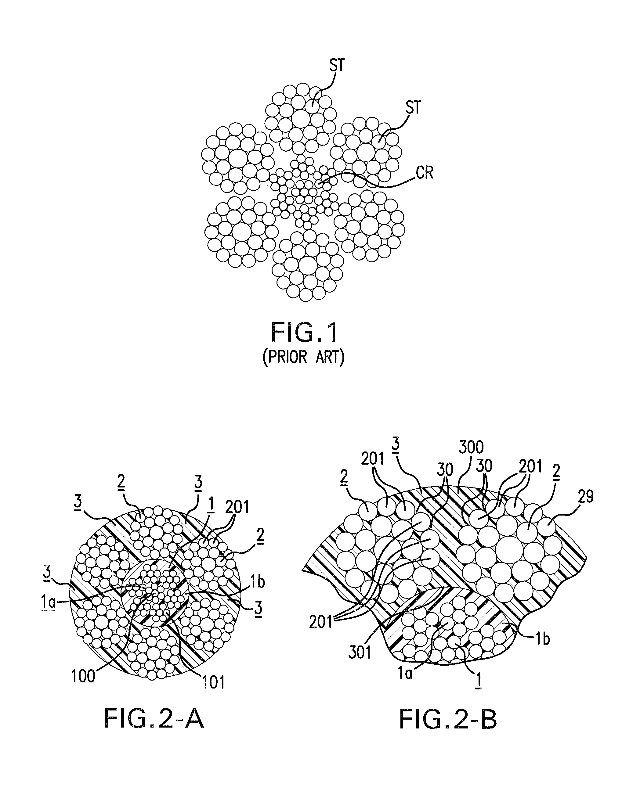
[0058]A rope is fabricated having a structure of IWRC 6×Fi (29) shown in FIG. 2-A, having 0 / 0, diameter 16 mm, a tensile strength 173 kN. There is used a core rope having a diameter 7.5 mm coated with polypropylene resin by an extruding mold machine at an outer periphery of a core rope main body. 6 pieces of side strands having a diameter of 5.01 mm are used.

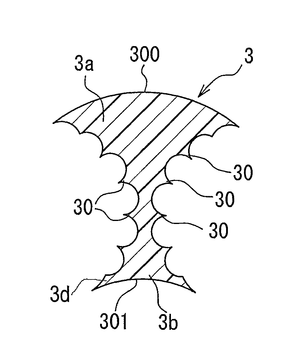
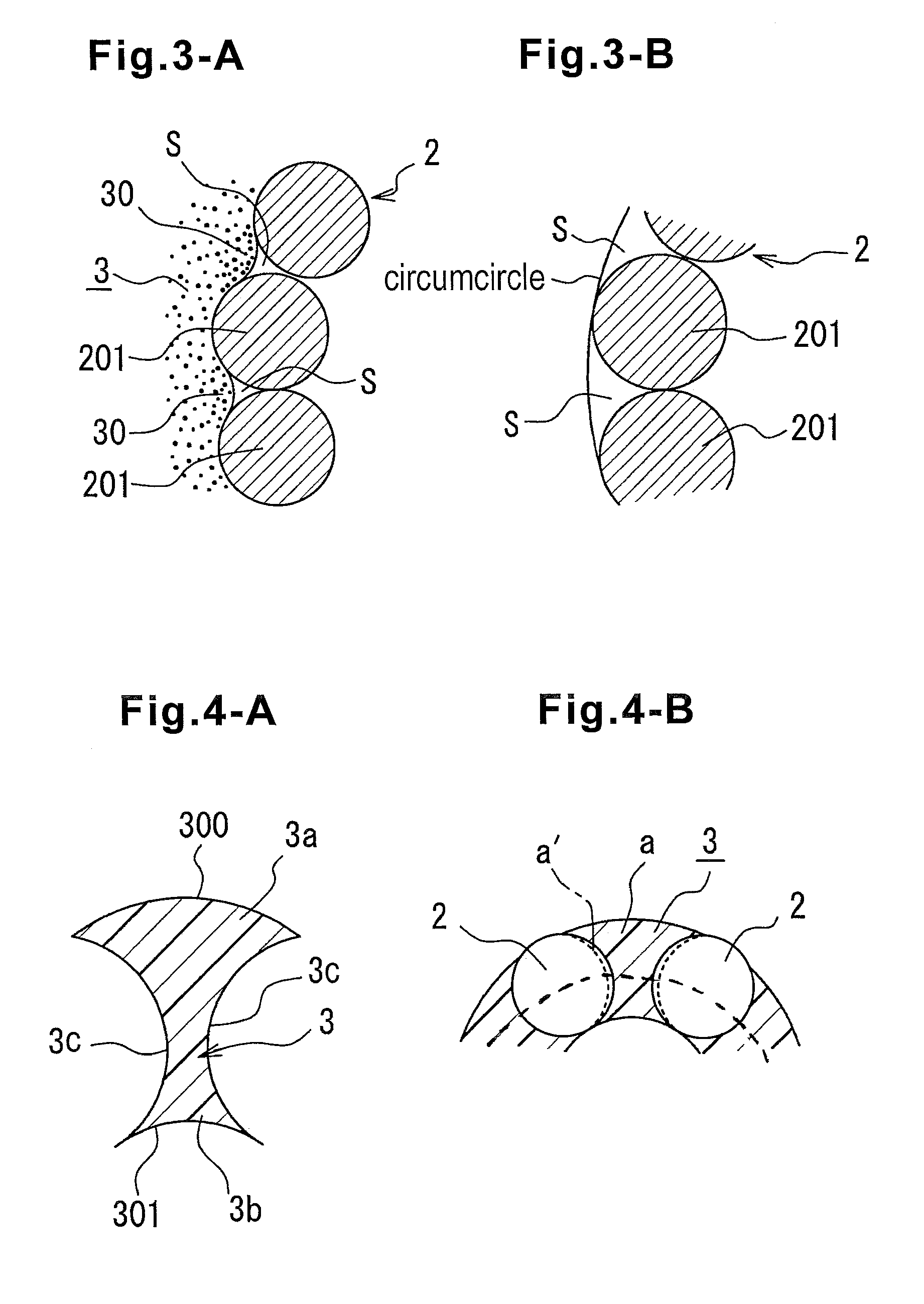
[0059]A resin spacer is a streak member formed by subjecting polypropylene resin to extrusion molding. The resin spacer is provided with a sectional shape shown in FIG. 4-A, and when a gap of arranging wire cores of the side strands is constituted by 100, a thickness thereof is constituted by a dimension of 125% thereof. The resin spacer is inserted between the side strands by the method of FIG. 5 and is plastically deformed by exerting a compression force in a radial direction by a vise. In order to determine a preferable condition, a radial direction compression degree is changed by varying an inner diameter of the vise to pro...


PUM

PropertyMeasurementUnit
angleaaaaaaaaaa
diameteraaaaaaaaaa
thicknessaaaaaaaaaa

Abstract

A wire rope for a running wire, has a core rope, a plurality of side strands arranged at an outer periphery of the core rope to be twisted together therewith, and a resin spacer interposed between the side strands, the core rope including a core rope main body composed of a plurality of wires and a resin coating layer outwardly surrounding the core rope main body so that the resin coating layer separates the core rope main body from the side strands, each of the side strands being composed of a plurality of further wires, and the resin spacer being provided with contour corresponding to an outer layer of the further wires of the side strands and extending between the wires of the outer layer of the side strands.

Description

CROSS-REFERENCE TO RELATED APPLICATION[0001]The invention described and claimed hereinbelow is also described in Japanese Patent Application JP 2007-090569 filed on Mar. 30, 2007. This Japanese Patent Application provides the basis for a claim of priority of invention under 35 U.S.C. 119(a)-(d).TECHNICAL FIELD[0002]The present invention relates to an improvement in a wire rope for a running wire.BACKGROUND ART[0003]There are many wire ropes. It is well known that when a wire rope is used, unless a wire rope is adapted to an object thereof and a place of use is selected, an advantage provided by a wire rope cannot sufficiently be utilized.[0004]Particularly, a wire rope for a running wire in a crane or the like is bent by a sheave and is wound to a drum. Therefore it must have an adequate fatigue resistance.[0005]A rope of this kind is known in the prior art, as shown by FIG. 1. It has a plurality of pieces of side strands ST at an outer periphery of a core rope CR to be twisted, and...

Claims


Application Information

Patent Timeline
Patent Type & Authority Patents(United States)
IPC IPC(8): D02G3/02
CPCD07B1/0673D07B1/167D07B3/04D07B3/06D07B1/165D07B2201/2037D07B2201/1032D07B2201/1036D07B2201/104D07B2201/2059D07B2201/2062D07B2201/2065D07B2201/2073D07B2201/2074D07B2201/2075D07B2501/2076
Inventor FURUKAWA, IPPEIIDA, SHUJI
Owner TOKYO ROPE MFG
Why Eureka
Try Eureka