
Method for controlling concavo-convex appearance on the working surface when processing round head by milling cutter

A technology of workpiece surface and ball end milling cutter, which is applied in the direction of metal processing machinery parts, metal processing, automatic control devices, etc., can solve the problems that the blade phase difference cannot be set, the circumferential positioning function cannot be set, and the frictional resistance can be reduced. , increase wear resistance, increase the effect of uniformity

Inactive Publication Date: 2004-10-06
SHANGHAI JIAOTONG UNIV
View PDF0 Cites 0 Cited by
  • Summary
  • Abstract
  • Description
  • Claims
  • Application Information

AI Technical Summary

Problems solved by technology

However, the CNC milling machines used in actual processing generally do not have the function of circumferential positioning, that is to say, the phase difference of the blade for each feed cannot be set during the processing

Method used


Image

  • Method for controlling concavo-convex appearance on the working surface when processing round head by milling cutter
  • Method for controlling concavo-convex appearance on the working surface when processing round head by milling cutter
  • Method for controlling concavo-convex appearance on the working surface when processing round head by milling cutter

Examples


Embodiment Construction

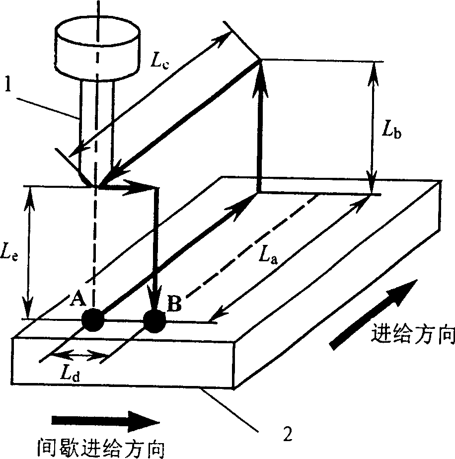
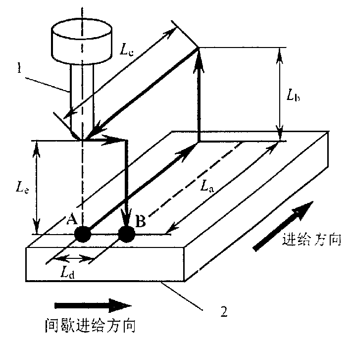
[0018] Such as figure 1 As shown, in actual processing, due to the feeding distance L of the milling cutter 1 a , back distance L c and the feed distance L d is fixed, so only the tool lift distance L b and feed distance L e to adjust the moving distance of the milling cutter, and the lifting distance L b and feed distance L e are equal, that is to say, the desired concave and convex shape can be obtained by adjusting the distance of lifting the knife.

[0019] Material of workpiece 2: brass; material of milling cutter 1: solid carbide, radius of milling cutter 1 is 5 mm; cutting depth of 0.2 mm; spindle speed n=250 rpm; inclination angle of milling cutter 1 is 15°; Feed speed v a =v b =v c =v d =v e = 250 mm / min; L a = L c = 100 mm, L d = 0.5 mm.

[0020] (a) When L b = L e When = 0.750 millimeters, by formula (1)-formula (3), obtain blade phase difference ω=0 °, according to the actual machining result, the pit of machined surface corresponds neatly up and d...


PUM


Abstract

A method for controlling the concave-convex degree on the surface of workpiece which is machined by rose cutter features that the moving pitch of rose cutter on the numerally controlled milling machine is controlled for getting ideal phase difference of cutting edge, resulting in lower surface roughness decreased by 30-40%.

Description

technical field [0001] The invention relates to a method for controlling the concave-convex pattern on the surface of a workpiece, in particular to a method for controlling the concave-convex pattern on the surface of the workpiece when a ball-end milling cutter is used, and belongs to the field of mechanical processing technology. Background technique [0002] In CNC milling, in order to improve the processing efficiency, while continuously increasing the spindle speed, the feed rate is also continuously increased, that is, the feed rate per revolution of the spindle is increased (hereinafter referred to as the feed rate per spindle revolution) as "feed rate"). The feed rate used in cutting abroad sometimes even reaches 0.4-0.5 mm / rev. After literature search, it was found that Zhao Minming and others wrote an article in "Journal of the Society of Precision Engineering" (Japan), 1998, 64 (12) 1826-1830, "5-axis Yuboyiruendomiru machining ni おける surface roughness generation...

Claims


Application Information

Patent Timeline
Patent Type & Authority Patents(China)
IPC IPC(8): B23C3/00B23C3/02B23Q15/00B23Q15/14B23Q15/22
Inventor 赵晓明
Owner SHANGHAI JIAOTONG UNIV
Learn More