High-vacuum optical fiber F-P pressure sensor

A pressure sensor, F-P technology, applied in the direction of fluid pressure measurement using optical methods, etc., can solve the problems of residual gas in the F-P cavity, the reduction of vacuum, and the influence of the accuracy of the F-P pressure sensor, and achieve strong conductivity and strength. Effect

Active Publication Date: 2016-10-05
CHENGDU KAITIAN ELECTRONICS
View PDF7 Cites 13 Cited by
  • Summary
  • Abstract
  • Description
  • Claims
  • Application Information

AI Technical Summary

Problems solved by technology

However, these F-P pressure sensors still have difficult problems at present, such as the related F-P pressure sensors disclosed in Chinese Patent Publication No. CN103644987A and CN103698080A, the pressure-sensitive diaphragm (silicon material) and the glass groove are connected by anodic bonding. Formation of F-P cavity
However, limited by the current technological level, it is difficult for the residual gas vacuum in the F-P

Method used


Image

  • High-vacuum optical fiber F-P pressure sensor

Examples


Example Embodiment

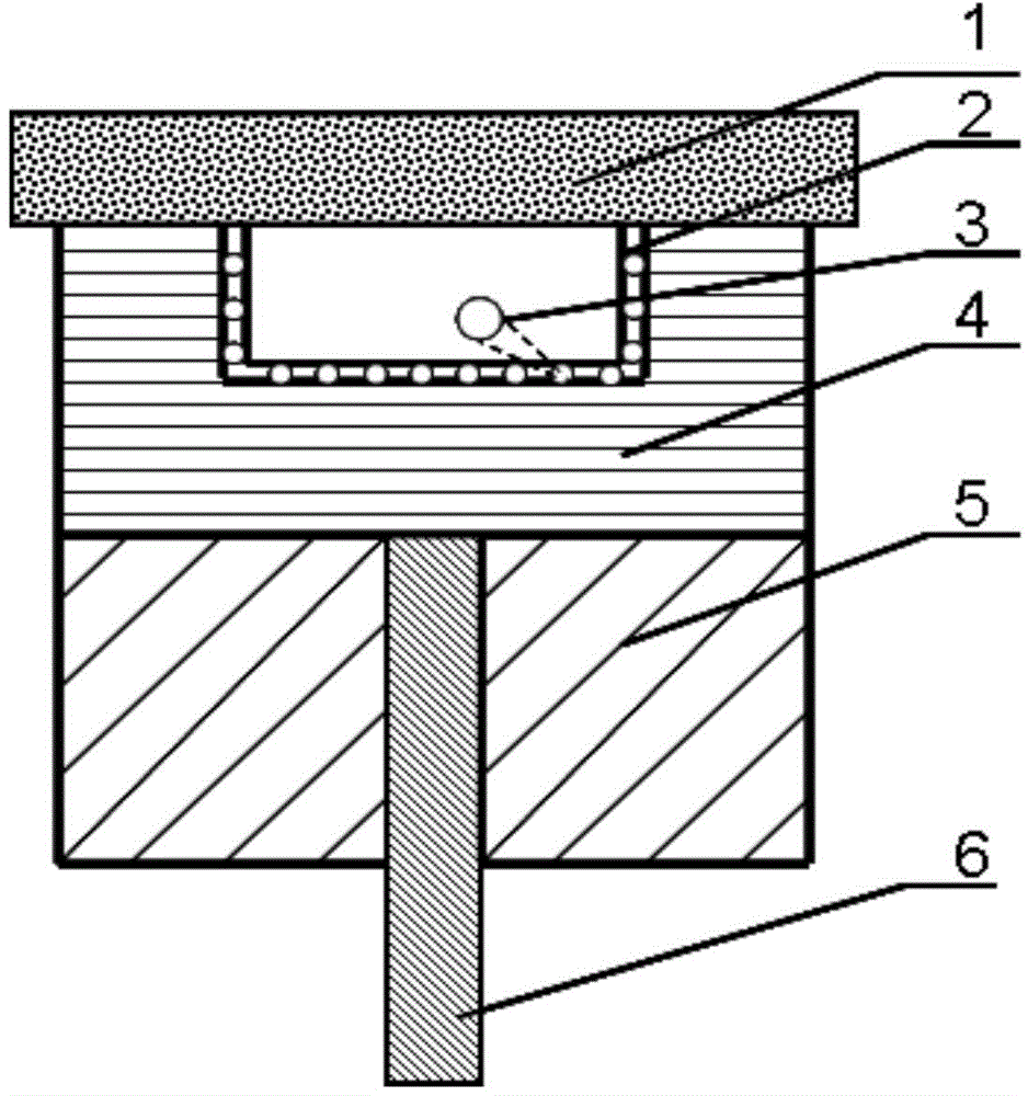
[0012] See figure 1 . In the embodiments described below, the high-vacuum optical fiber F-P pressure sensor is composed of a pressure diaphragm 1, a graphene film 2, a gas adsorption nanoparticle 3, an upper ferrule 4, a lower ferrule 5, and an optical fiber 6. The upper ferrule 4 has a groove, and the bottom surface and four walls of the groove are covered with a layer of nanoparticles 3 used to absorb the residual gas in the FP cavity and are wrapped by the graphene film 2. The pressure diaphragm 1 is connected with the upper ferrule 4 to form an FP The cavity, the bottom surface of the groove and the four walls are covered with adsorption nanoparticles 3 used to adsorb the residual gas in the FP cavity. The adsorption nanoparticles 3 are wrapped by the graphene film 2, and the pressure diaphragm 1 is connected with the upper ferrule 4 to form the FP cavity. The ferrule 4 and the lower ferrule 5 are integrated by interconnection. A part of the optical fiber 6 is inserted in...


PUM

PropertyMeasurementUnit
Thicknessaaaaaaaaaa

Abstract

The invention discloses a high-vacuum optical fiber F-P pressure sensor, which comprises a pressure-sensitive diaphragm, an upper insert core, a lower insert core and an optical fiber coated inside the lower insert core. The upper insert core (4) is provided with a groove. A layer of nanoparticles (3) for absorbing residual gases in an F-P cavity is covered onto the bottom surface and the periphery of the groove, and is wrapped by a graphene film (2). The pressure-sensitive diaphragm (1) and the upper insert core (4) are connected to form the F-P cavity. The upper insert core (4) and the lower insert core (5) are connected with each other as a whole. One part of the optical fiber is inserted into the lower insert core, and the other part of the optical fiber is located outside the lower insert core. The optical fiber is connected with a demodulation device as a conductive fiber. The upper insert core and the lower insert core are connected with each other as a whole. The high-vacuum optical fiber F-P pressure sensor is simple in structure, convenient and rapid to manufacture, and low in cost. The high-vacuum optical fiber F-P pressure sensor solves the problem in the prior art that the vacuum degree of residual gases in the F-P cavity cannot be smaller than 1 Kpa.

Description

Technical field [0001] The invention belongs to the technical field of optical fiber sensing, and particularly relates to a graphene structure high vacuum optical fiber F-P pressure sensor. Background technique [0002] Optical fiber sensor technology started at the end of the 1970s and was developed with optical fiber communication technology. The optical fiber sensor uses light as the information carrier and optical fiber as the transmission medium for sensing and measuring the measured parameters. It has good electrical insulation, strong anti-electromagnetic interference capability, high temperature resistance, high pressure, corrosion resistance, and can be used in harsh environments such as inflammable and explosive. Fiber optic Fabry-Perot (F-P) sensor is an important branch of fiber optic sensor. Optical fiber FP sensor has the advantages of simple structure, small size, high reliability, high sensitivity, short response time, single optical fiber signal transmission, e...

Claims


Application Information

Patent Timeline
IPC IPC(8): G01L11/02
Inventor 孙波熊菠梅运桥
Owner CHENGDU KAITIAN ELECTRONICS
Why Eureka
Try Eureka