Turbine blade with impingement cooling

a technology of impingement cooling and turbine blades, which is applied in the direction of liquid fuel engines, vessel construction, marine propulsion, etc., can solve the problems of long service increase creep and fatigue strength, etc., and achieve the effect of improving the life of the turbine blade, reducing the notch effect, and increasing creep and fatigue strength

Active Publication Date: 2006-06-20
ROLLS ROYCE DEUT LTD & CO KG
View PDF13 Cites 18 Cited by
  • Summary
  • Abstract
  • Description
  • Claims
  • Application Information

AI Technical Summary

Benefits of technology

[0006]A broad aspect of the present invention is to provide a design of a turbine blade of the type described above which decreases the load peaks in the area of the impingement air channels, thus increasing the fatigue and the creep strength and, ultimately, the life of the turbine blade, with the weight of the turbine blade remaining essentially unchanged.
[0008]The present invention realizes that the partitions are coolest in the center area and represent a zone of maximum tensile stress. In the turbine blades according to the state of the art, the stress concentrations are particularly high in this area, this being due to the fact that this area accommodates the entries of the impingement air channels which are straight-lined and inclined to obtain a specific angle of air impact. According to the present invention, the impingement air channels are now curved such that the position and the angle of impingement air exit remain unchanged and the impingement air is directed onto the inner surface of the respective outer wall section at a specific angle, while the air entry and, thus, the entire impingement air channel is re-located towards a hotter end area of the partition where lower tensile stresses apply. The impingement air channel is concave with regard to the outer wall and entirely extends near, and virtually parallel to, the hot outer wall. This form and arrangement of the impingement air channels reduces the notch effect and increases the creep and fatigue strength, thus improving the life of the turbine blade. Furthermore, the decrease in stress concentration so obtained permits smaller partition wall thicknesses in the area of the impingement air channels, thus enabling the weight of the turbine blade to be reduced.
[0009]In accordance with a further, significant feature of the present invention, the cross-sectional area of the impingement air channels has the shape of an oblong hole or an oval, with the longitudinal axis of the oval or oblong hole extending in the longitudinal direction of the cooling air chamber. This cross-sectional shape, its radial orientation and the resultant low notch factor also improve the creep and fatigue characteristics and, thus, increase the life of the turbine blade. Furthermore, the wall thickness of the partitions can be reduced, enabling the weight of the turbine blade to be decreased. It was found that, in particular, the combination effect between the impingement air channel curvature, which allows the impingement air channels to be fully routed in the hot area of the partitions, and the above mentioned cross-sectional shape and orientation yield an unexpected increase in creep and fatigue strength, resulting in a long service life of the turbine blade.

Problems solved by technology

It was found that, in particular, the combination effect between the impingement air channel curvature, which allows the impingement air channels to be fully routed in the hot area of the partitions, and the above mentioned cross-sectional shape and orientation yield an unexpected increase in creep and fatigue strength, resulting in a long service life of the turbine blade.

Method used


Image

  • Turbine blade with impingement cooling
  • Turbine blade with impingement cooling

Examples


Embodiment Construction

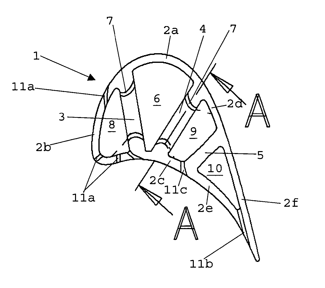
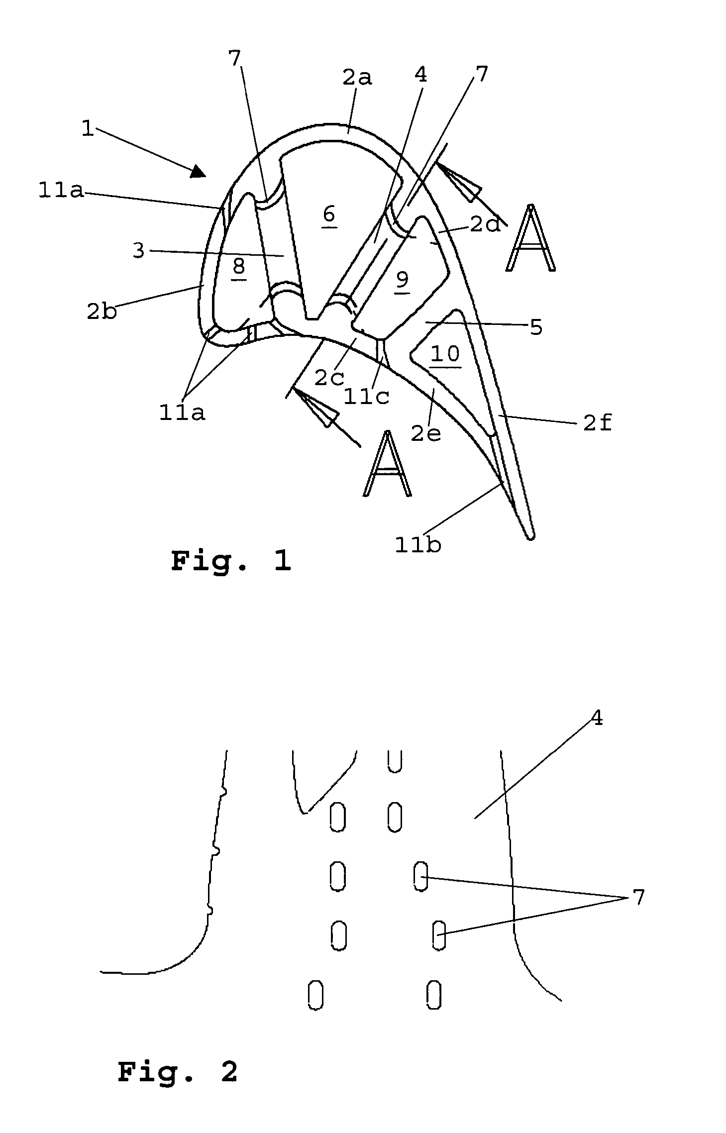
[0013]The airfoil 1 of a high-pressure turbine blade comprises a thin-walled outer wall 2 and supporting inner partitions 3 to 5. The first and second supporting partitions 3 and 4 together with an outer wall section 2a confine a cooling air chamber 6 into which cooling air tapped from the compressor of the gas turbine is continuously introduced. In the end area of the first and second partition 3 and 4, i.e. in the vicinity of the outer wall, impingement air channels 7 are arranged which are concave with regard to the outer wall, originate at the cooling air chamber 6 and issue into the first or the second impingement air cooling chamber 8 or 9, respectively. The impingement air cooling chamber 8 is confined by the first partition 3 and an outer wall section 2b, while the second impingement air cooling chamber 9 is formed by the second partition 4, two outer wall sections 2c, 2d and the third partition 5. The third partition 5 and two outer wall sections 2e, 2f enclose a further co...


PUM


Abstract

A hollow turbine blade cooled with compressor air is divided into a cooling air chamber (6) and into impingement air cooling chambers (8, 9) by inner, supporting partitions (3, 4). The cooling air is conveyed from the cooling air chamber into the impingement air cooling chamber via impingement air channels (7) provided in the partitions. The impingement air channels are concave with regard to the adjacent outer wall (2) of the blade airfoil (1) and arranged completely in the hot area near the outer wall and, in addition, have an oblong or elliptical cross-section whose longitudinal axis agrees with the radial orientation of the turbine blade. By reduced stress concentration in the area of the impingement air channels, the fatigue and creep characteristics are improved and life is increased.

Description

[0001]This application claims priority to German Patent Application DE10332563.8, filed Jul. 11, 2003, the entirety of which is incorporated by reference herein.BACKGROUND OF THE INVENTION[0002]This invention relates to a turbine blade with impingement cooling of the thermally highly loaded outer wall sections, where at least one partition is provided in the interior of the hollow turbine blade to form a cooling-air chamber supplied with cooling air and where, with the formation of an impingement air cooling chamber, the partition is provided with a plurality of impingement air channels to apply cooling air to the remotely adjacent inner surface of the hot outer wall sections.[0003]The efficiency of gas turbines can be improved by increasing the combustion chamber temperatures. Such temperature increase is, however, limited by the thermal loadability of the components exposed to the hot gases, in particular the stator vanes and rotor blades in the turbine stage downstream of the com...

Claims


Application Information

Patent Timeline
Patent Type & Authority Patents(United States)
IPC IPC(8): F01D5/18
CPCF01D5/18F01D5/187F05D2250/14F05D2260/201F05D2250/712
Inventor DAVISON, PETERBLUME, BARBARA
Owner ROLLS ROYCE DEUT LTD & CO KG
Why Eureka
Try Eureka