
Ligating band dispenser with transverse ridge profile

a technology of transverse ridge and dispenser, which is applied in the field of tissue ligation, can solve the problems of excessive room in the endoscope working channel, preventing the use of catheter-type accessory devices, and affecting the ligation effect of the band, so as to promote the rolling of the band instead of sliding, and improve the transverse groove or ridge profile

Inactive Publication Date: 2006-06-20
BOSTON SCI SCIMED INC
View PDF20 Cites 8 Cited by
  • Summary
  • Abstract
  • Description
  • Claims
  • Application Information

AI Technical Summary

Benefits of technology

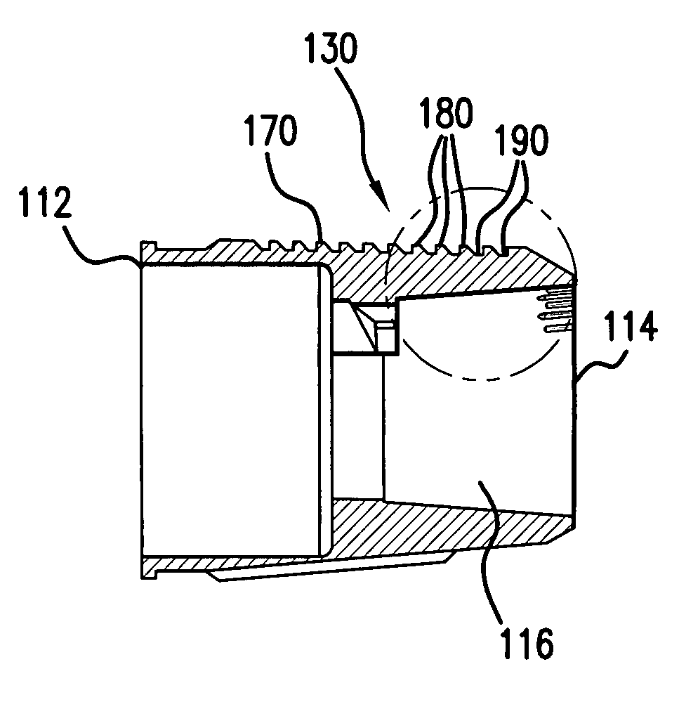
[0010]The present invention is directed toward providing an improved distal end for a ligating band dispenser, wherein the device has an improved transverse groove or ridge profile that promotes rolling of the bands instead of sliding.
[0011]In one embodiment, the ligating bands and the transverse grooves or ridges on the support surface are dimensioned such that the width of the bands when stretched on the support surface is substantially the same as the pitch of the transverse grooves or ridges on the support surface. In another embodiment, the ligating bands and the transverse grooves or ridges on the support surface are dimensioned such that the width of the bands when stretched on the support surface is less than the pitch of the transverse grooves or ridges on the support surface. Having the width of the bands when stretched on the support surface be substantially the same as or less than the pitch of the transverse grooves or ridges on the support surface allows the bands to fit within the grooves. This helps insure that the bands are sufficiently held back by the ridge crests to induce a rolling action.

Problems solved by technology

The effect of the inward pressure applied by the band is to stop all circulation through the targeted tissue, thereby causing the tissue to die.
These pull strings may interfere with each other, may become tangled, or may take up excessive room in the endoscope working channel, thereby preventing the use of catheter-type accessory devices.
The reduced friction may cause the ligating bands to slide instead of roll along the support surface, and hence may reduce the probability of a successful band deployment.

Method used


Image

  • Ligating band dispenser with transverse ridge profile
  • Ligating band dispenser with transverse ridge profile
  • Ligating band dispenser with transverse ridge profile

Examples


Embodiment Construction

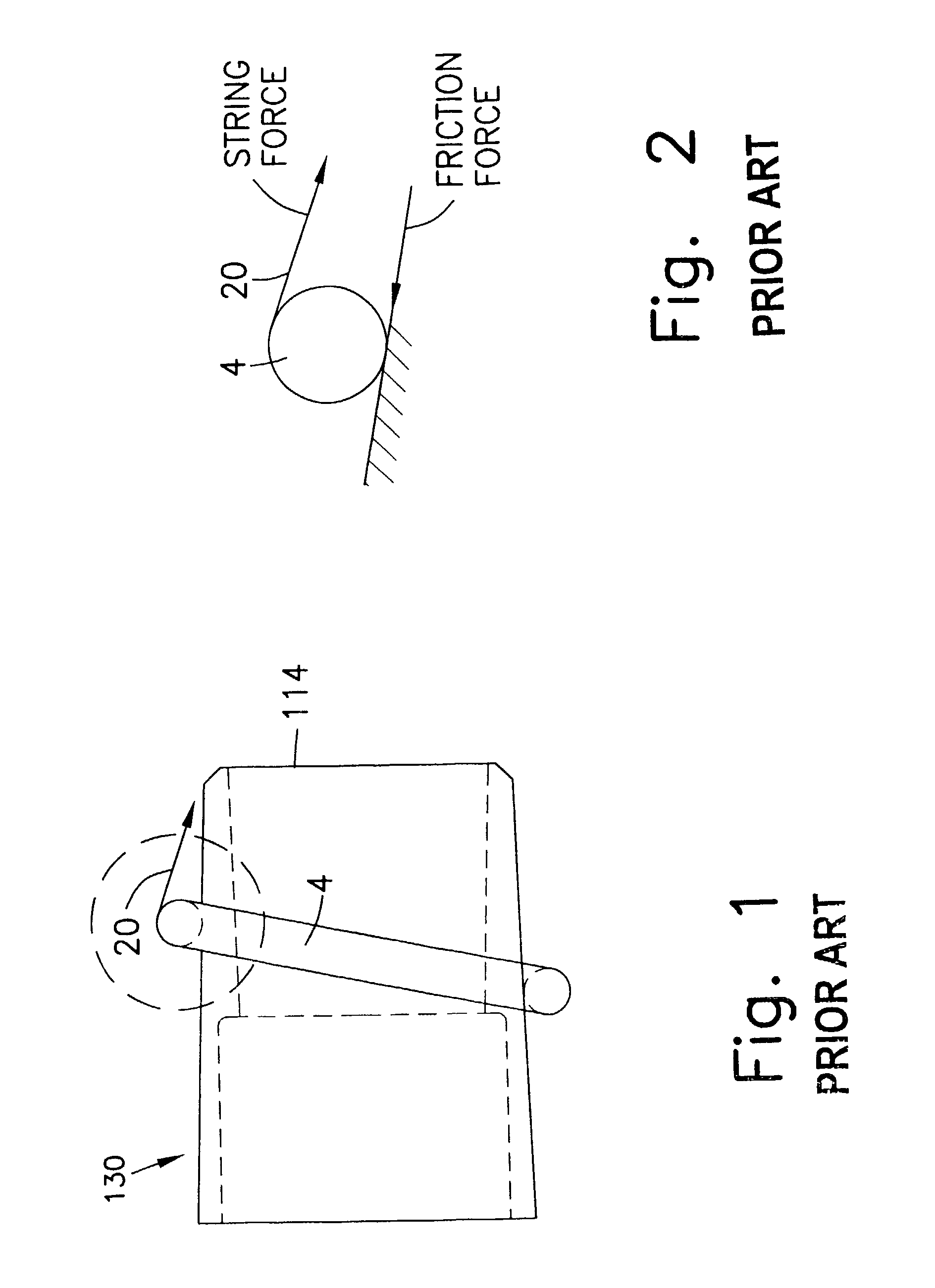
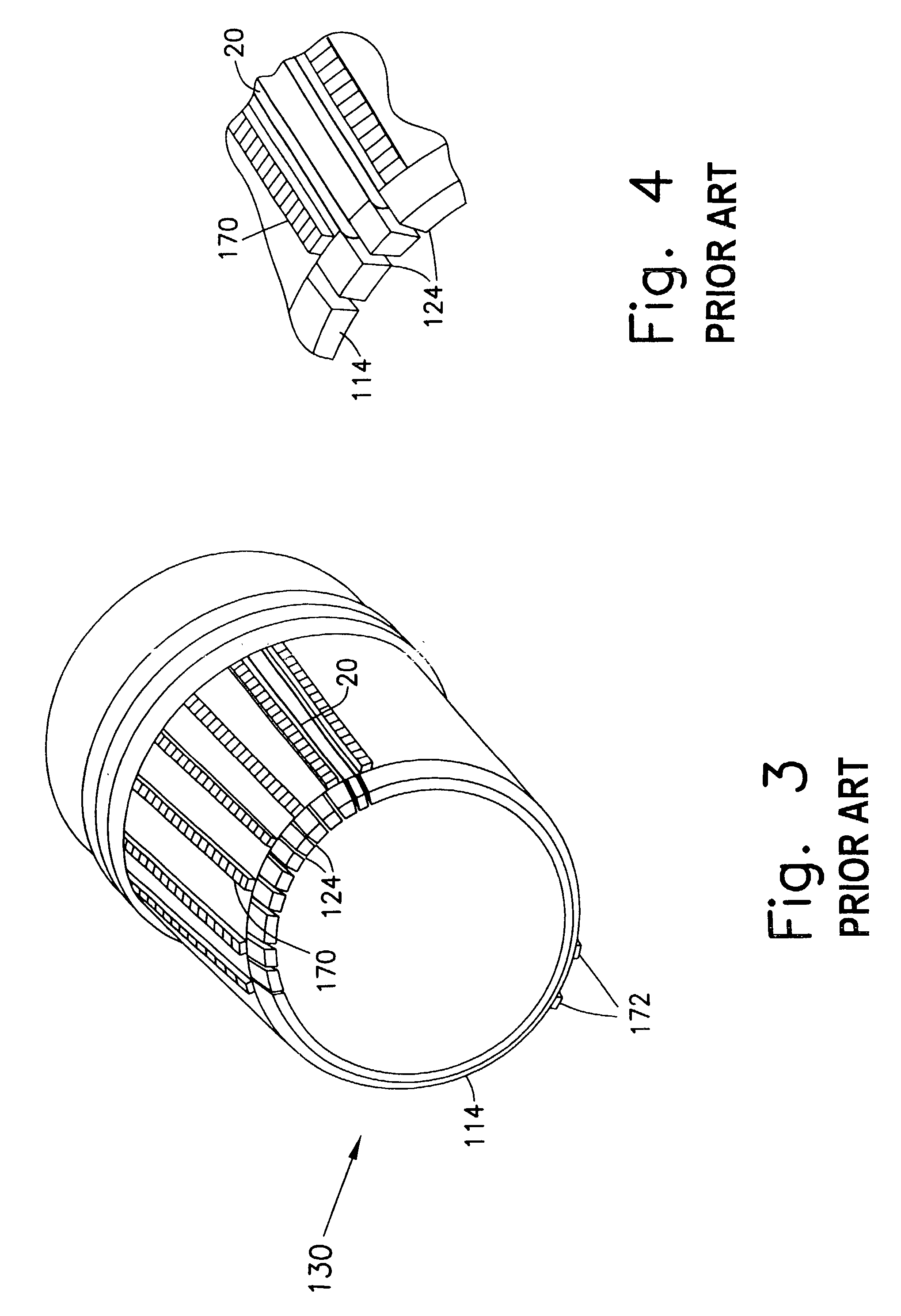
[0023]FIGS. 1 and 2 illustrate the forces involved in the deployment of a ligating band 4, FIG. 2 being an expanded view of the highlighted portion of FIG. 1. In any design in which the bands 4 are pulled towards the distal end 114 of a support surface 130, reliable band deployment is facilitated by the bands rolling rather than sliding across the support surface 130. The rolling action is caused, for example, by the trigger line 20 pulling over the top of the band 4 and by friction between the band 4 and the support surface 130. Rolling is initiated, for example, at the point in which the trigger line 20 contacts the band 4, and propagates around the band circumference. This rolling causes the band 4 to move distally.

[0024]Potential problems are created when the band 4 slides instead of rolls. If the band 4 slides across the support surface 130, that portion of the band 4 at the trigger line 20 may reach the distal rim of the support surface, thereby allowing the trigger line 20 to...


PUM


Abstract

An improved distal end for a ligating band dispenser having a transverse groove or ridge profile that promotes rolling of the bands. In one embodiment, the ligating bands and the transverse grooves or ridges are dimensioned such that the width of the bands when stretched on the support surface is substantially the same as the pitch of the transverse grooves or ridges. In another embodiment, the ligating bands and the transverse grooves or ridges are dimensioned such that the width of the bands when stretched on the support surface is less than the pitch of the transverse grooves or ridges. Having the width of the bands when stretched on the support surface be substantially the same as or less than the pitch of the transverse grooves or ridges allows the bands to fit within the grooves, which helps insure that the bands are sufficiently held back by the ridge crests to induce a rolling action. In addition, the transverse grooves or ridges may also be dimensioned such that the height of the ridge crests is sufficiently high to insure that the bands are sufficiently held back by the ridge crests to induce a rolling action.

Description

FIELD OF THE INVENTION[0001]The present invention relates generally to the field of tissue ligation, and more particularly to an improved distal end for a device for dispensing ligating bands.BACKGROUND INFORMATION[0002]Physicians have used elastic ligating bands to treat lesions, including internal hemorrhoids and mucositis and for performing mechanical hemostasis. The object of such ligation is to position a ligating band, which is usually elastic, over the targeted lesion or blood vessel section by first stretching the band beyond its undeformed diameter and then drawing the tissue to be ligated within the band. Thereafter the band is released so that it contracts, applying inward pressure on the section of tissue caught within the band. The effect of the inward pressure applied by the band is to stop all circulation through the targeted tissue, thereby causing the tissue to die. The body then sloughs off the dead tissue, or the dead tissue may be aspirated into an endoscope or a...

Claims


Application Information

Patent Timeline
Patent Type & Authority Patents(United States)
IPC IPC(8): A61B17/10A61B17/12A61B19/00
CPCA61B17/12013A61B2017/00296A61B2017/12018A61B2017/00907
Inventor FORTIER, RICHARD
Owner BOSTON SCI SCIMED INC
Learn More