Millimeter wave communications system with a high performance modulator circuit

a communication system and modulator circuit technology, applied in the field of millimeter wave communications system with high-performance modulator circuit, can solve the problems of reducing the performance of conventional modulators, affecting the efficiency of communication, and affecting the quality of communication, so as to achieve efficient spatial and directional partitioning and high data rate communication

Inactive Publication Date: 2006-06-20
TREX ENTERPRISES CORP
View PDF22 Cites 74 Cited by
  • Summary
  • Abstract
  • Description
  • Claims
  • Application Information

AI Technical Summary

Problems solved by technology

However, when either of the modulation rate or RF frequency increase to the range of about 50 GHz, these conventional modulators suffer diminished performance.
Unfortunately, when one looks at the higher frequencies, the performance of this diode switch degrades rapidly as 60 GHz is approached.
At this frequency, the amount of reflection becomes comparable with the amount of transmission and hence the notion of a good “on” state becomes seriously compromised.
Unfortunately, when one looks at the higher frequencies, the performance of this diode switch degrades rapidly as 60 GHz is approached.
At this frequency, the amount of transmission become comparable with the amount of reflection and hence the notion of a good “off” state also becomes seriously compromised.
Thus, during a conductive transition there is a time when the switching process is very inefficient.
The communication range is also limited.
However, as these point-to-point wireless communication links proliferate, the need to prevent interference between nearby links increases, especially when these links are operating on the same or overlapping frequencies.
Although millimeter-wave communication links are normally designed for narrow beams, there exists the possibility that two closely located links may interfere with each other, or that energy reflected from structures, terrain, or other objects may bounce into and along the path of another communication link, causing interference. FIG. 13A illustrates a group of point-to-point communications links that are operating in a non-interfering basis. FIG. 13B illustrates the same link but an obstruction 40, such as a building or a tree, produces some reflection of some of the transmitted signal resulting in the potential for one of the signals to interfere with one or more of the others.
This protocol of operation reduces the chances of newly deployed data links interfering with pre-existing data links.

Method used


Image

  • Millimeter wave communications system with a high performance modulator circuit
  • Millimeter wave communications system with a high performance modulator circuit
  • Millimeter wave communications system with a high performance modulator circuit

Examples


first preferred embodiment

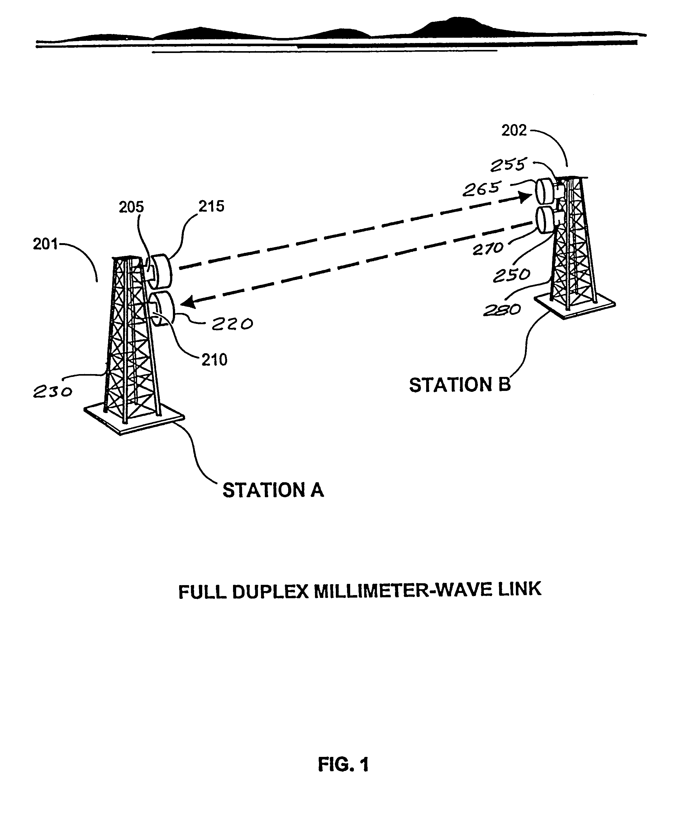
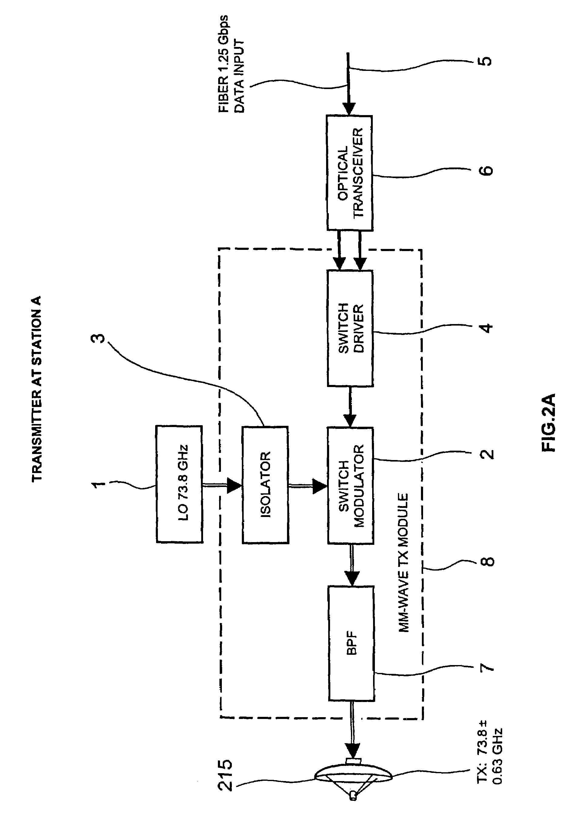
[0075]In a first preferred embodiment built and tested by Applicants, a millimeter-wave data link is configured to pass Ethernet data packets bi-directionally between the ends of the link. A block diagram of the data link is shown in FIG. 14. A block diagram of the millimeter-wave transceiver used at each end of the link is illustrated in FIG. 15. One end of the link 42 (designated as “Transceiver A”) transmits at 72 GHz and receives at 75 GHz, and the other end 44 (designated as “Transceiver B”) transmits at 75 GHz and receives at 72 GHz. Dish antennas 24 with a diameter of 2 feet and feedhorns 51 are used at each end to achieve a radiated beam width of approximately 0.34 degrees.

[0076]The received signal strength at end A is used to control the power transmitted by link end B. The received signal strength at link end B is used to control the power transmitted by link end A. The signal strength received at A is communicated to end B via the data stream flowing from A to B. The sign...


PUM


Abstract

A high data rate communication system operating at frequencies greater than 70 MHz and at data rates of about 1.25 Gbps or greater. Preferred embodiments include modulators with a resonant LC circuit including a diode which is back-biased for “off” (i.e., no transmit) and forward biased for “on” (or transmit). The modulator is a part of high performance transceivers for wireless, millimeter wave communications links. A preferred embodiment provides a communication link of more than eight miles which operates within the 71 to 76 GHz portion of the millimeter spectrum and provides data transmission rates of 1.25 Gbps with bit error rates of less than 10−10 . A first transceiver transmits at a first bandwidth and receives at a second bandwidth both within the above spectral range. A second transceiver transmits at the second bandwidth and receives at the first bandwidth. The transceivers are equipped with antennas providing beam divergence small enough to ensure efficient spatial and directional partitioning of the data channels so that an almost unlimited number of transceivers will be able to simultaneously use the same spectrum. In a preferred embodiment the first and second spectral ranges are 71.8+ / −0.63 GHz and 73.8+ / −0.63 GHz and the half power beam width is about 0.2 degrees or less. Preferably, a backup transceiver set is provided which would take over the link in the event of very bad weather conditions. In other embodiments especially useful for mobile applications at least one of the transceivers include a GPS locator.

Description

[0001]This application is a continuation in part application of application Ser. No. 09 / 847,629 filed May 2, 2001, now U.S. Pat. No. 6,556,836 B2; application Ser. No. 10 / 046,348 filed Oct. 25, 2001 now abandoned, application Ser. No. 10 / 001,617 filed Oct. 30, 2001, now abandoned; application Ser. No. 09 / 992,251 filed Nov. 13, 2001, now abandoned; application Ser. No. 10 / 000,182 filed Dec. 1, 2001, now abandoned; application Ser. No. 10 / 025,127 filed Dec. 18, 2001 now abandoned, application Ser. No. 10 / 041,083 filed Jan. 5, 2002, now U.S. Pat. No. 6,611,696 B2; application Ser. No. 10 / 044,556 filed Jan. 11, 2002, now U.S. Pat. No. 6,587,699 B2; application Ser. No. 10 / 061,872 filed Jan. 31, 2002, now abandoned; application Ser. No. 10 / 127,886 filed Apr. 23, 2002 now abandoned; and application Ser. No. 10 / 196,486 filed Jul. 15, 2002 all of which are incorporated by reference herein.[0002]The present invention relates to communication systems and specifically to high data rate wireles...

Claims


Application Information

Patent Timeline
Patent Type & Authority Patents(United States)
IPC IPC(8): H04B1/40H03C3/00H01Q1/12H01Q19/10H04B1/38H04B1/52H04B7/04H04B10/10
CPCH01Q1/125H01Q19/10H04B1/3805H04B10/40H04B10/1123H04B10/1149H04B1/52H04B7/0408
Inventor LOVBERG, JOHNCHEDESTER, RICHARDJOHNSON, PAULSLAUGHTER, LOUIS
Owner TREX ENTERPRISES CORP
Why Eureka
Try Eureka