Antenna and antenna packaging structure

An antenna and antenna radiator technology, which is applied to the connection of the antenna grounding switch structure, the antenna grounding device, the antenna, etc., can solve the problems of limited and no change in the working mode of the microstrip antenna, and achieve the effect of widening the antenna gain bandwidth.

Inactive Publication Date: 2018-12-07
HUIZHOU SPEED WIRELESS TECH CO LTD +1
View PDF9 Cites 16 Cited by
  • Summary
  • Abstract
  • Description
  • Claims
  • Application Information

AI Technical Summary

Problems solved by technology

The current chip packaging process is rapidly developing towards miniaturization and high integration. If the antenna is to be packaged on the chip, the designed antenna must have the characteristics of broadband, high gain, and low profile. However, the existing antenna structure is difficult Meet these requirements at the same time, including using the EBG (Electromagnetic Band Gap) structure as the reflector or ground of the antenna to reduce the profile of the antenna. For example, when the ground of the microstrip antenna is an EBG structure, the height of the microstrip antenna will be reduced, but the working mode of the microstrip antenna has not changed, and it is still the fundamental mode TM10. In addition, the gain of the microstrip antenna will increase a little due to the suppression of the surface wave, but it is also relatively limited

Method used


Image

  • Antenna and antenna packaging structure
  • Antenna and antenna packaging structure
  • Antenna and antenna packaging structure

Examples


Embodiment 1

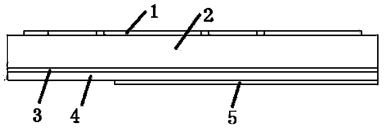
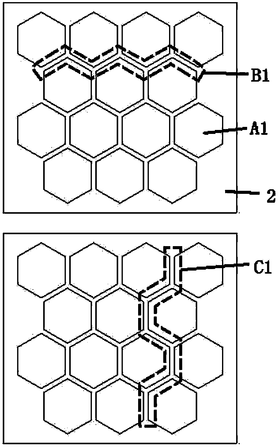
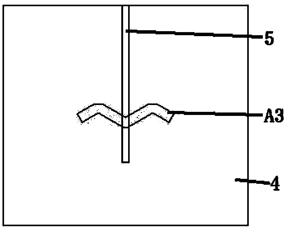
[0058] refer to Figure 1-3 , the antenna radiator is formed by a periodic array of 14 hexagonal metal sheet units A1, the radiation gap B1 formed between adjacent hexagonal metal sheet units in the non-radiation direction and the hexagonal hexagonal blocks in the radiation direction The non-radiative gap C1 formed between the hexagonal metal sheet units makes it form a periodic structure with 14 gaps capacitively loaded, changing the width of the radiation gap and the non-radiative gap formed between adjacent hexagonal metal sheet units can improve the performance of the antenna bandwidth. image 3 It is the schematic diagram of the back side of the antenna. The feeding form of the antenna adopts the slot coupling feeding form. There is a W-shaped feeding slot in the center of the grounded metal plate. The microstrip feeder couples the electromagnetic energy to the antenna radiator through the W-shaped feeding slot. By adjusting the micro With feeder stub length to improve i...

Embodiment 2

[0061] refer to Figure 4 , this embodiment is similar to Embodiment 1, but the arrangement of the antenna radiator is changed. The antenna radiator is composed of 10 hexagonal metal sheet units and 4 semi-hexagonal metal sheet units. Cut off half of the polygonal element, and the size of the non-radiating side of the antenna becomes smaller.

Embodiment 3

[0063] refer to Figure 5 , this embodiment is similar to Embodiment 1, the difference is that the center of each hexagonal metal sheet unit is loaded with a metal via D1 connected to the ground metal plate, the radiation slot and the non-radiation slot and the metal via hole make each Parallel capacitance and series inductance are formed between metal sheet units, and the gap formed between adjacent metal sheets along the direction of the feeder will generate electromagnetic radiation, which excites two modes, TM10 and TM20, to form broadband characteristics.


PUM


Abstract

The invention relates to an antenna, which comprises an antenna radiator, an antenna dielectric substrate, a grounded metal plate, and a feed structure. The antenna radiator, the antenna dielectric substrate and grounded metal plate are connected in sequence. The antenna radiator consists of a plurality of metal sheet units. The coupled slots between the adjacent metal sheet units form radiation slots, a feed slot is formed in the grounded metal plate, the feed structure provides a feed source to the feed slot, and the feed structure and the radiation slot is fed by a radiation slot through coupling. The invention further provides an antenna packaging structure. An EBG structure is deployed as part of the antenna radiator to solve the problems of high profile and narrow bandwidth of the traditional antennas. The antenna has the advantages of low profile, broadband, high gain and the like, is very suitable for millimeter wave band AiP, is also suitable for mass production at low cost, and can be widely used in 60 GHz WiFi system and a future 5G millimeter wave communication system.

Description

technical field [0001] The invention relates to the field of wireless communication, in particular to an antenna and a packaged antenna structure. Background technique [0002] In recent years, with the development of mobile communications, wireless communication systems have higher and higher requirements on data transmission rates, so it is required that communication systems can provide larger and larger bandwidths to meet application requirements. As the front-end hardware device of the communication system, the broadband antenna is indispensable. In recent years, many broadband antenna design methods have been proposed, such as antenna loading, non-frequency-variable antenna, traveling wave antenna, multi-mode technology, broadband feeder network, etc. For antennas in the millimeter wave frequency band, considering the loss of this frequency band, the AiP (Antenna in Pack) antenna solution, that is, the package antenna solution, is generally used. The current chip pac...

Claims


Application Information

Patent Timeline
Patent Type & Authority Applications(China)
IPC IPC(8): H01Q1/38H01Q1/50H01Q9/04H01Q1/12
CPCH01Q1/12H01Q1/38H01Q1/50H01Q9/0407H01Q5/342H01Q13/106H01Q13/18H01Q15/006H01Q15/008H01Q19/09H01P3/026H01P3/08H01P3/081H01Q1/48
Inventor 李琴芳俞斌史艳梅
Owner HUIZHOU SPEED WIRELESS TECH CO LTD
Why Eureka
Try Eureka