Antenna and an antenna packaging structure

a technology of antenna and packaging structure, applied in the field of wireless communication, can solve the problems that the above-mentioned traditional antenna structure is difficult to meet these requirements, and achieve the effects of simple structure, high gain and convenient processing

Active Publication Date: 2018-11-29
HUIZHOU SPEED WIRELESS TECH CO LTD +1
View PDF0 Cites 17 Cited by
  • Summary
  • Abstract
  • Description
  • Claims
  • Application Information

AI Technical Summary

Benefits of technology

[0018]The antenna element radiation pattern of the present disclosure is a broadside pattern. The antenna element in this disclosure does not need a clearance area, and it only needs a certain height, which is suitable for mounting in a package body of a chip. The antenna element in this disclosure has a high gain characteristic about 10 dBi, which is suitable for the millimeter wave communication, since the feeder line loss and space transmission loss are very large in this band. The antenna element gain bandwidth in this disclosure is very wide and the antenna element gain is high in the whole impedance bandwidth, which can meet the gain demand of the bands in different countries.
[0019]The antenna element in this disclosure is suitable for forming an array antenna, which is very suitable for realizing beamforming and phased array applications in the millimeter wave band in the 5G mobile terminals. The antenna array consists of a group of antenna elements that can transmit signals independently. The beam forming of antenna array is realized by adjusting the amplitude and phase of each antenna element. The antenna element in this disclosure has a simple structure. It is easy to process and needs no complex structures to increase the bandwidth of the antenna (such as loaded cavity, multi-layer structure, the frequency-independent antenna or travelling wave antenna, etc.), and it can achieve mass production by AiP packaging process.

Problems solved by technology

But the aforementioned traditional antenna structures are difficult to meet these requirements, even with the use of an electromagnetic band-gap (EBG) structure as the reflector or the ground of the antenna to reduce the profile of the antenna.

Method used


Image

  • Antenna and an antenna packaging structure
  • Antenna and an antenna packaging structure
  • Antenna and an antenna packaging structure

Examples


embodiment 1

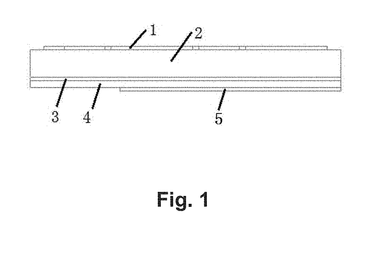
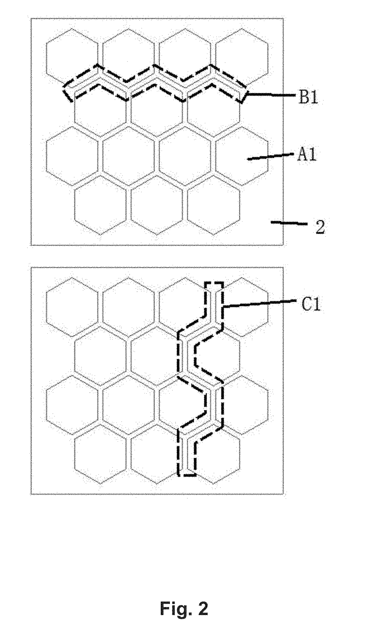
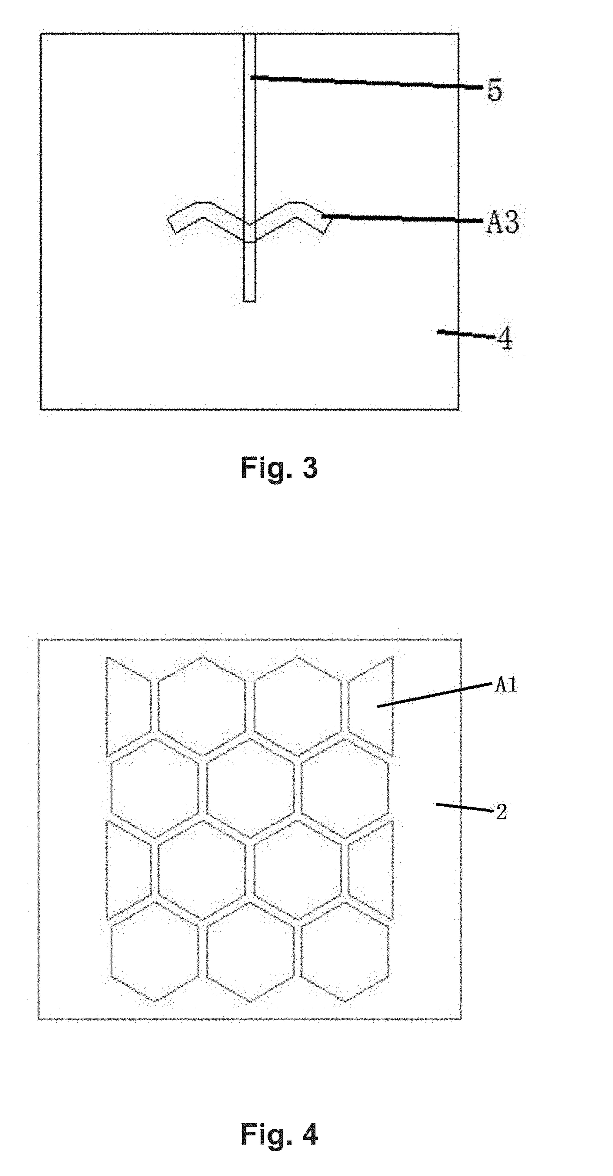
[0039]As shown in FIGS. 1-3, an antenna radiator is arranged repetitively or periodically 14 hexagonal metal sheet units A1. The radiation slots B1 formed by six adjacent hexagonal sheet units in a direction of non-radiation and the non-radiation slots C1 formed by six adjacent hexagonal metal sheet units in the direction of radiation form a capacitive loading periodic structure. The antenna bandwidth is improved by adjusting the width of the radiation slots and non-radiation slots. FIG. 3 shows the back view of the antenna. The antenna feed structure uses slot coupled feed structure. The electromagnetic energy of the microstrip feeder line is coupled the antenna radiator through a W shape feed slot at the center of grounded metal plate. The impedance matching characteristic of the antenna element can be improved by adjusting the of the microstrip feeder line open stub. In addition, the center of the W shape feed slot and the center of radiation slot at the center of the periodical ...

embodiment 2

[0041]As shown in FIG. 4, this embodiment is similar to the embodiment 1, but the arrangement of the antenna radiator is different. The antenna radiator consists of 10 hexagonal metal sheet units and 4 half hexagonal sheet units. The edge size of the antenna element is reduced in the non-radiation direction when the hexagonal units at the both ends of the non-non-radiation direction are cut off half.

embodiment 3

[0042]As shown in FIG. 5, this embodiment is similar to embodiment 1. The difference is that the metal vias D1 connected with the grounded metal plate is located at the center of each hexagon metal sheet unit. The radiation slots, the non-radiation slots, and the metal vias form an equivalent parallel capacitance and an equivalent series inductance between each metal sheet unit. The antenna element will produce electromagnetic radiation from the slots between adjacent metal sheet units along the direction of the feeder line, so the TM10 mode and TM20 mode can be excited simultaneously which form a broadband characteristic.


PUM


Abstract

An antenna element includes an antenna radiator, an antenna dielectric substrate, a grounded metal plate, and a feed structure. The antenna radiator consists of several metal sheet units. The coupled slots between the adjacent metal sheet units form radiation slots and the grounded metal plate has a feed slot which is fed by the feed structure and the radiation slot is fed by the feed slot through coupling. This disclosure also provides an antenna packaging structure. An EBG is deployed as part of the radiator to improve the problems of high profile and narrow bandwidth of the traditional antennas. The EBG radiator also achieves low profile, broadband and high gain characteristics that is very suitable for millimeter wave band AiP and is also suitable for mass production at low cost, and therefore it can be widely used in 60 GHz WiFi system and a 5G millimeter wave communication system.

Description

FIELD OF THE DISCLOSURE[0001]This disclosure relates generally to the technical field of wireless communications. More specifically, this disclosure relates to an antenna and an antenna packaging structure.BACKGROUND[0002]In recent years, the demand for the data transmission rate of a wireless communication system is higher and higher with the development of mobile communication, so the wider bandwidth of the communication system is needed to meet the requirements of the applications. As the most frontend hardware of the communication system, a broadband antenna is essential. There have been many ways of realizing broadband antennas, such as antenna loading, frequency-independent antenna, travelling-wave antenna, multimode technology, broadband feed network, and so on. For an antenna of a millimeter-wave band, an AiP (Antenna in Package) solution is normally adopted, considering the loss of the transmission line in this [0003]The current chip packaging technology is moving rapidly t...

Claims


Application Information

Patent Timeline
Patent Type & Authority Applications(United States)
IPC IPC(8): H01Q13/10H01Q1/50H01Q1/48
CPCH01Q13/106H01Q1/50H01Q1/48H01P3/026H01P3/08H01P3/081H01Q1/12H01Q1/38H01Q9/0407H01Q5/342H01Q13/18H01Q15/006H01Q15/008H01Q19/09
Inventor YU, BINLI, QINGFANGSHI, YANMEI
Owner HUIZHOU SPEED WIRELESS TECH CO LTD
Why Eureka
Try Eureka