Single-chip CMOS direct-conversion transceiver

Inactive Publication Date: 2006-06-20
MICRON TECH INC
View PDF29 Cites 57 Cited by
  • Summary
  • Abstract
  • Description
  • Claims
  • Application Information

AI Technical Summary

Problems solved by technology

Compared to other types of integrated circuits, the level of integration in the RF sections of transceivers is

Method used


Image

  • Single-chip CMOS direct-conversion transceiver
  • Single-chip CMOS direct-conversion transceiver
  • Single-chip CMOS direct-conversion transceiver

Examples


Embodiment Construction

[0032]In the following description of the exemplary embodiment, reference is made to the accompanying drawings which form a part hereof, and in which is shown by way of illustration the specific embodiment in which the invention may be practiced. It is to be understood that other embodiments may be utilized as structural changes may be made without departing from the scope of the present invention.

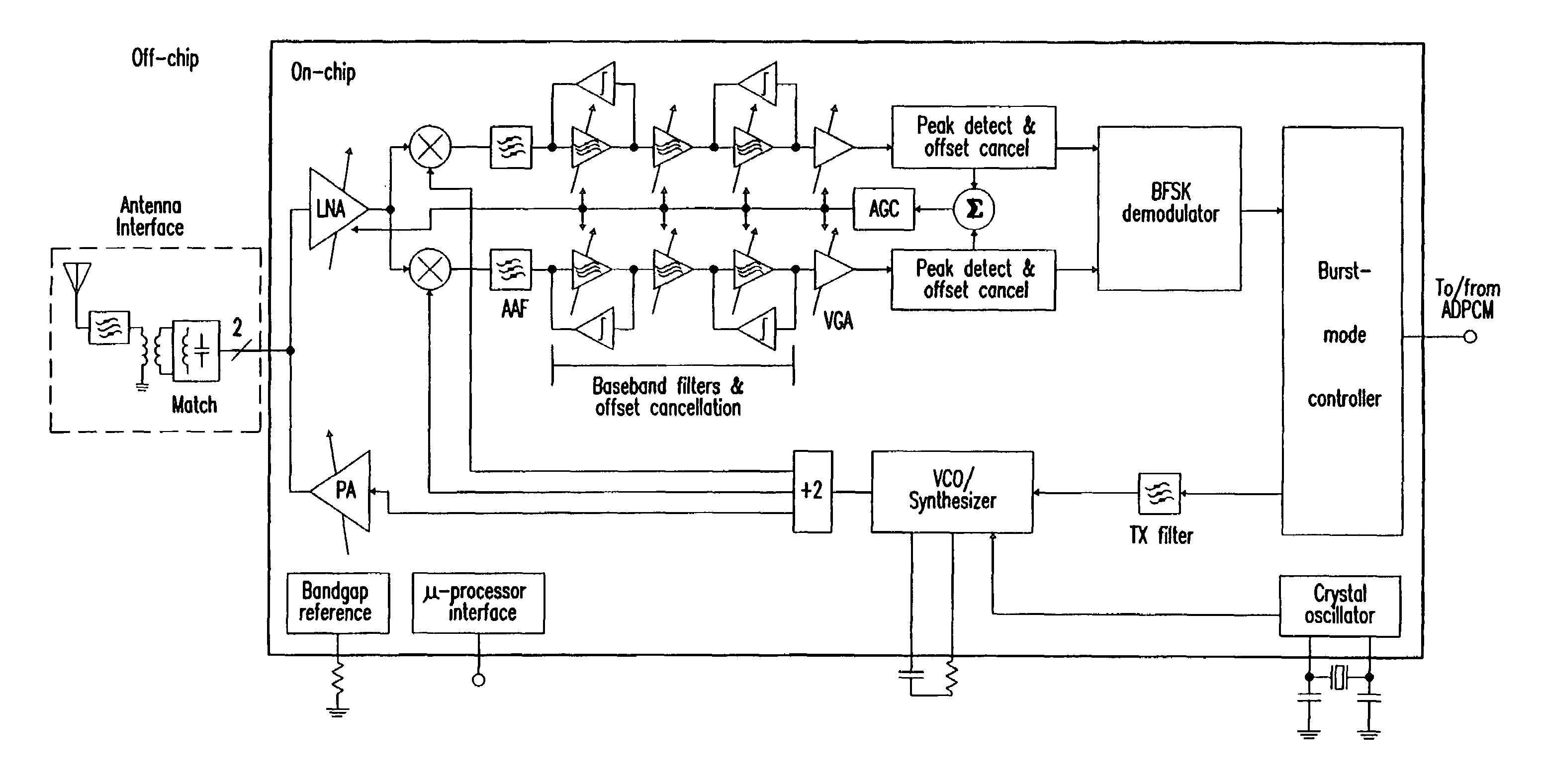
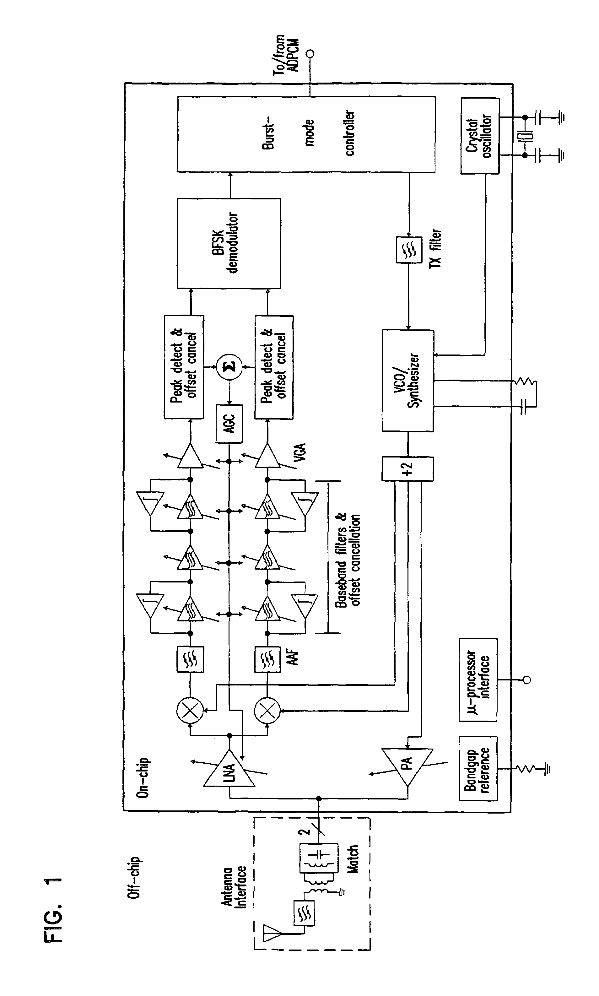
[0033]In an embodiment of the present invention is a specific combination of building blocks that realize a monolithic transceiver for digital communication that may be used for various media.

[0034]A function of the monolithic transceiver is to convert digital data to an analog signal suitable for transmission and to convert a received analog signal into digital data. In practice, there will be a finite bit error rate in the transmission, propagation and reception processes. The specific BER that is tolerable depends on the application. In some cases, the input to one monolithic transceive...


PUM


Abstract

A single-chip CMOS direct conversion transceiver includes an RF circuit, a transmitter having a synthesizer, a receiver having a baseband filter, and a demodulator. The synthesizer is coupled to the RF circuit. The baseband filter is coupled to the RF circuit and the synthesizer. The demodulator is coupled to the baseband filter. The RF circuit, the synthesizer, the baseband filter, and the demodulator are arranged and configured in CMOS devices and provide a complete interface between an antenna and a voiceband codec.

Description

[0001]This application claims the benefit of Provisional Application No. 60 / 099,723, filed Sep. 10, 1998.BACKGROUND OF THE INVENTION[0002]1. Field of the Invention[0003]This invention relates in general to communication systems, and more particularly to a single-chip CMOS direct-conversion transceiver.[0004]2. Description of Related Art[0005]Today's wireless communications markets are being driven by a multitude of user benefits. Products such as cellular phones, cordless phones, pagers, and the like have freed corporate and individual users from their desks and homes and are driving the demand for additional equipment and systems to increase their utility. As a result digital radio personal communications devices will play an increasingly important role in the overall communications infrastructure in the next decade.[0006]Mixed-signal integration and power management have taken on added importance now that analog and mixed analog-digital ICs have become the fastest-growing segment ...

Claims


Application Information

Patent Timeline
IPC IPC(8): H04B1/44
CPCH04B1/48
Inventor MACNALLY, DONALD EVANCHO, THOMAS B.RABII, SHAHRIARMEHTA, SRENIK SURESHNILSON, CHRISTOPHER DONALDMACK, MICHAEL PETERPLOUVIER, LAURENCE MARGUERITEMARRINGA, MENNODUKATZ, ERIC S.
Owner MICRON TECH INC
Why Eureka
Try Eureka