Dissolving filter cake

a filter cake and filter technology, applied in the direction of fluid removal, wellbore/well accessories, chemistry apparatus and processes, etc., can solve the problems of reduced pump rate, inability to allow, and no longer mobile slurry

Inactive Publication Date: 2006-06-27
SCHLUMBERGER TECH CORP
View PDF19 Cites 126 Cited by
  • Summary
  • Abstract
  • Description
  • Claims
  • Application Information

AI Technical Summary

Benefits of technology

[0061]A further advantage to the method of the Invention is that the operator need not design a job that will screen out. Thus in situations in which the operator may not wish to decrease the pad volume, slow the pumps, decrease the proppant loading, or make other design changes, he may still screen out when he chooses by adding base. Thus, although it is an option to design the treatment so that screenout would probably occur even without the addition of base and then to add base in order to ensure a screenout, it is equally within the scope of the Invention to design a treatment that probably will not screen out without the addition of base, and then to add base. It is also within the scope of this Invention to design and start pumping a treatment that is not designed or expected to screen out at any point during the treatment and then during the treatment to decide to cause the treatment to screen out and therefore at that point to add base and cause the screenout.

Problems solved by technology

High permeability formations to be hydraulically fractured are frequently poorly consolidated, so that sand control is also needed.
It is very undesirable to allow the proppant or gravel to pack the wellbore above the producing formation.
It is also very undesirable if, instead of generating a short, wide fracture, a fracturing or frac and pack treatment screens out too late or not at all, that is if the fracture keeps growing, in length and / or in height, beyond what is necessary and desired; then an optimal pack and the desired fracture size and shape are never generated to maximize production and to prevent flowback of proppant or sand.
In a tip screenout, the solids concentration at the tip of the fracture becomes so high due to fluid leak-off into the formation that the slurry is no longer mobile.
If a tip screenout is encountered in such a fracturing operation before the entire designed treatment is pumped, as inferred from an increase in pumping pressure, the pump rate is reduced or most likely the treatment is stopped and considered a failure.
Unfortunately, in spite of data-fracturing information, pressure transients collected by downhole pressure gauges during treatments have indicated that TSO's do not occur in many, perhaps the majority, of the treatments in which they are desired and intended.
Therefore, the desired fracture conductivity is not obtained.
First, the fracture may be too large for the proppant volume.
This occurs a) when the pad is too large or b) when the “efficiency” is too high, or c) when the ratio of proppant volume to slurry volume selected in the design of the job is not high enough.
Second, the fracture width may be too great for the proppant to form a bridge in the fracture.
This may be due to bad initial design (for example in choice of proppant diameter) or to width growth beyond what was expected.
This concentration is insufficient to cause bridging during pumping under the conditions at which it is normally employed, especially in low permeability formations.
However, the scheduling of the inclusion in the fluid of the filter cake degradation agent(s), and optional filter cake degradation agent aid(s), may be complicated.

Method used


Image

  • Dissolving filter cake
  • Dissolving filter cake

Examples


example 1

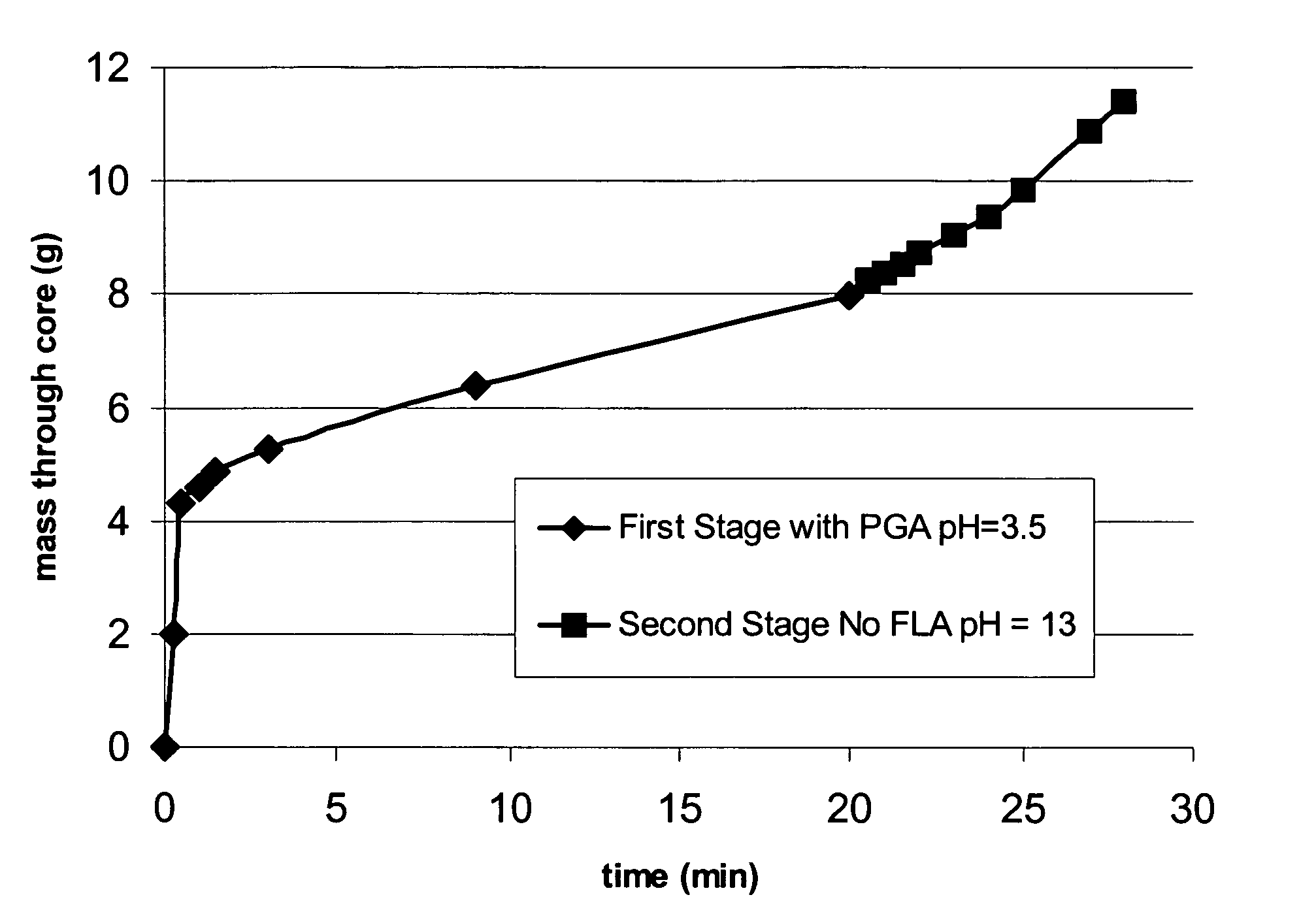
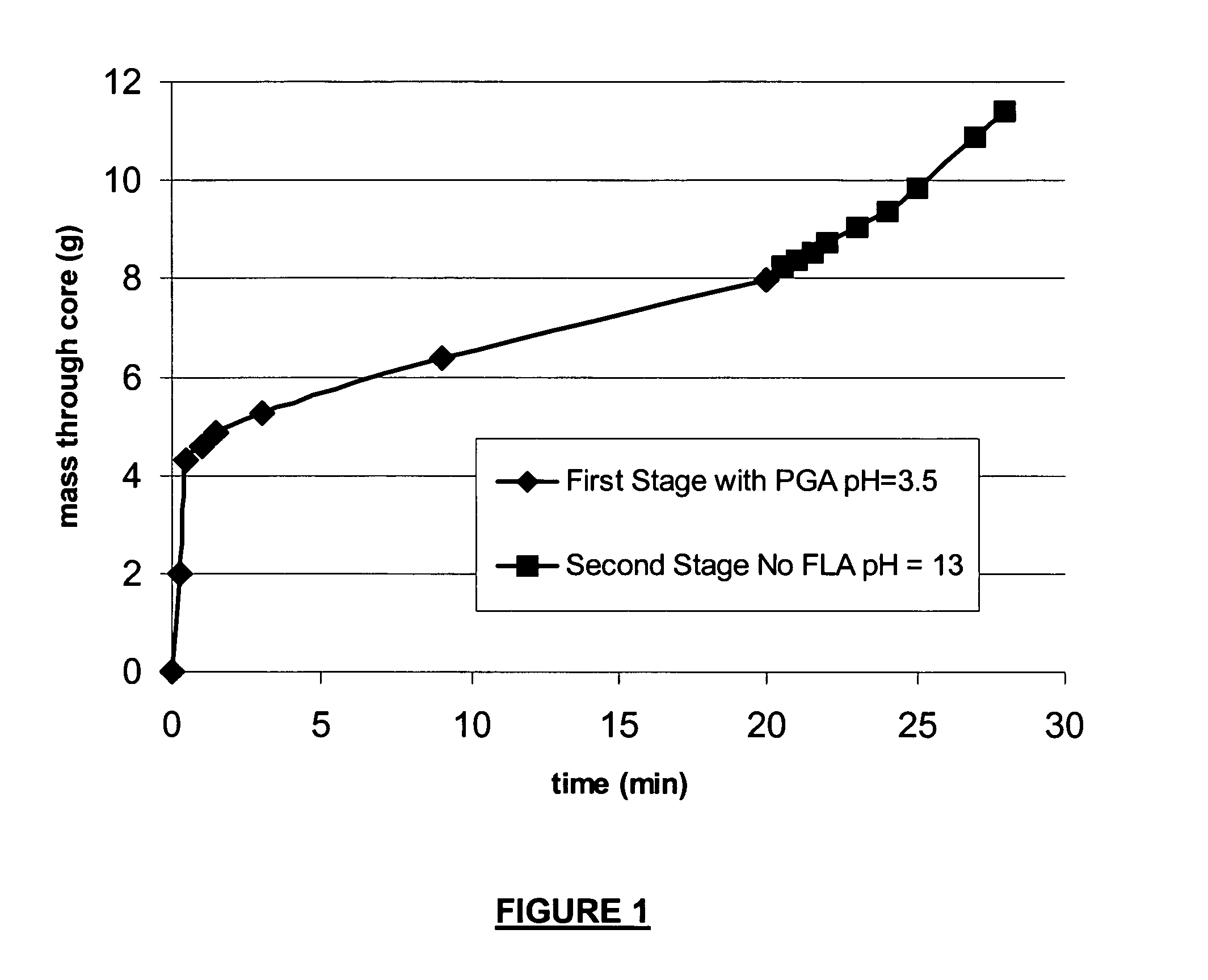
[0065]To demonstrate an embodiment of the Invention, a static fluid loss cell was set up with a Berea sandstone core of 200 mD permeability. A viscoelastic fluid containing PGA was prepared by dispersing 0.5 weight percent PGA in water, adding 0.2% sodium sesquicarbonate buffer to keep the pH at about 10, and then adding 6 weight percent of a concentrate that contained about 40 weight percent of erucic amidopropyl dimethyl betaine, about 5 weight percent sodium chloride, about 22 weight percent isopropanol, about 1 weight percent polynaphthalene sulfonate, and about 5 weight percent water. This fluid was prepared in a Waring blender at “moderate”speed. The PGA used was Dupont TLF 6267, described by the supplier as a crystalline material having a glass transition temperature of about 49° C., a melting point of about 200 to 210° C., a molecular weight of about 600, and a mean particle size of about 8 to 15 microns. This fluid was pumped through the core with a differential pressure of...

example 2

[0067]The ease of hydrolysis and dissolution of Dupont PGA TLF 6267 was determined by suspending samples of the PGA in water adjusted to different pH's. 0.2 Weight percent sodium sesquicarbonate was used to buffer at pH 10. For pH 12 the fluid was adjusted by adding either KOH and NaOH with identical results. The suspensions were heated to the desired temperature, held at that temperature without stirring for the indicated time, and the results were noted. The PGA was considered dissolved when none was visible in the solution to the unaided eye. Results are given in Table 1, and show how simple experiments can be used to determine the pH at which a given solid base-soluble material will dissolve at a given temperature in a given amount of time.

[0068]

pHTemperature, ° C.Dissolution time1066~10 hours1266  10116  


PUM

PropertyMeasurementUnit
melting pointaaaaaaaaaa
melt temperaturesaaaaaaaaaa

Abstract

Methods are presented to induce a screenout during a subterranean formation fracturing or combined fracturing and gravel packing treatment having a viscoelastic surfactant-based carrier fluid by laying down a filter cake at least a portion of which is a base-soluble material, injecting proppant slurry, and causing hydrolysis and dissolution of the solid base-soluble material by adding base so that leak-off increases, the concentration of proppant in the fracture increases, and the proppant screens out. A method of gravel packing with a viscoelastic surfactant-based carrier fluid by laying down a filter cake at least a portion of which is a base-soluble material, injecting gravel, and causing hydrolysis and dissolution of the solid base-soluble material by adding base. Methods of slowing or accelerating the hydrolysis and dissolution are given, and addition of bridging-promoting materials is included.

Description

CROSS REFERENCE TO RELATED APPLICATIONS[0001]This application is a Continuation-in-Part of U.S. patent application Ser. No. 10 / 227,690 filed on Aug. 26, 2002 now U.S. Pat. No. 6,938,693.BACKGROUND OF INVENTION[0002]This Invention relates to increasing the flow of fluids into or out of subterranean wells. More particularly it relates to stimulation of the flow of fluids from the rock of a formation into a wellbore. Most particularly it relates to methods of controlling the size and shape, location, and quality of fractures created in hydraulic fracturing (either conventional or with coiled tubing), or in fracturing and gravel packing in one operation, and to gravel packing.[0003]Hydraulic fracturing, gravel packing, and fracturing and gravel packing in one operation, are used extensively to stimulate the production of hydrocarbons, water and other fluids from subterranean formations. These operations involve pumping a slurry of “proppant” in hydraulic fracturing (natural or synthetic...

Claims


Application Information

Patent Timeline
Patent Type & Authority Patents(United States)
IPC IPC(8): E21B43/267C09K8/52C09K8/62C09K8/70C09K8/74C09K8/80
CPCC09K8/52C09K8/68C09K8/74C09K8/703Y10S507/924C09K8/50C09K8/5045C09K8/506C09K8/508C09K8/512C09K8/62C09K8/665C09K8/685C09K8/80E21B33/138E21B37/06E21B43/025E21B43/267
Inventor SULLIVAN, PHILIP F.BONEY, CURTIS L.
Owner SCHLUMBERGER TECH CORP
Why Eureka
Try Eureka