Tobacco dipping cup with saliva reservoir

a technology of drinking cup and dipping cup, which is applied in the field of drinking cups, can solve the problems of insufficient opening of empty soda cans to receive saliva, impractical use in driving a car or generally when indoors, and inability to clean up, so as to facilitate cleaning and deposit saliva. , the effect of avoiding the risk of contaminating the contents of the cup

Inactive Publication Date: 2006-06-27
WILSON CHRISTOPHER A
View PDF5 Cites 10 Cited by
  • Summary
  • Abstract
  • Description
  • Claims
  • Application Information

AI Technical Summary

Benefits of technology

[0012]The present invention comprises a beverage cup having a detachable saliva reservoir so that a user may enjoy a beverage and smokeless tobacco products simultaneously. The cup has a saliva conduit running from its upper extremity down to a saliva reservoir which screws on the bottom. The upper portion of the conduit is formed into a mouthpiece which allows the user to easily deposit the saliva without the risk of contaminating the contents of the cup. The beverage within the cup and the saliva reservoir are separated by an internal bulkhead. Cleaning is facilitated by the fact that the reservoir screws off the bottom. Both the cup and the reservoir can then be placed in a dishwasher or washed by hand.
[0015]2. To provide an ergonomic mouthpiece which allows the user to easily deposit the saliva into the reservoir;
[0016]3. To provide for easy cleaning of the device when it is not in use; and
[0017]4. To provide a device which can be made of molded plastic to minimize cost.

Problems solved by technology

This saliva intermingles with the tobacco and can cause sickness if swallowed.
This option is impractical when driving a car or generally when indoors.
As the can or cup is not really designed for this purpose, its use can be difficult.
As one example, empty soda cans do not have a sufficiently large opening to receive the saliva.
1. Do not provide a good design for receiving saliva; and
2. Require the carrying of two separate vessels if the user wishes to drink a beverage.

Method used


Image

  • Tobacco dipping cup with saliva reservoir
  • Tobacco dipping cup with saliva reservoir
  • Tobacco dipping cup with saliva reservoir

Examples


Embodiment Construction

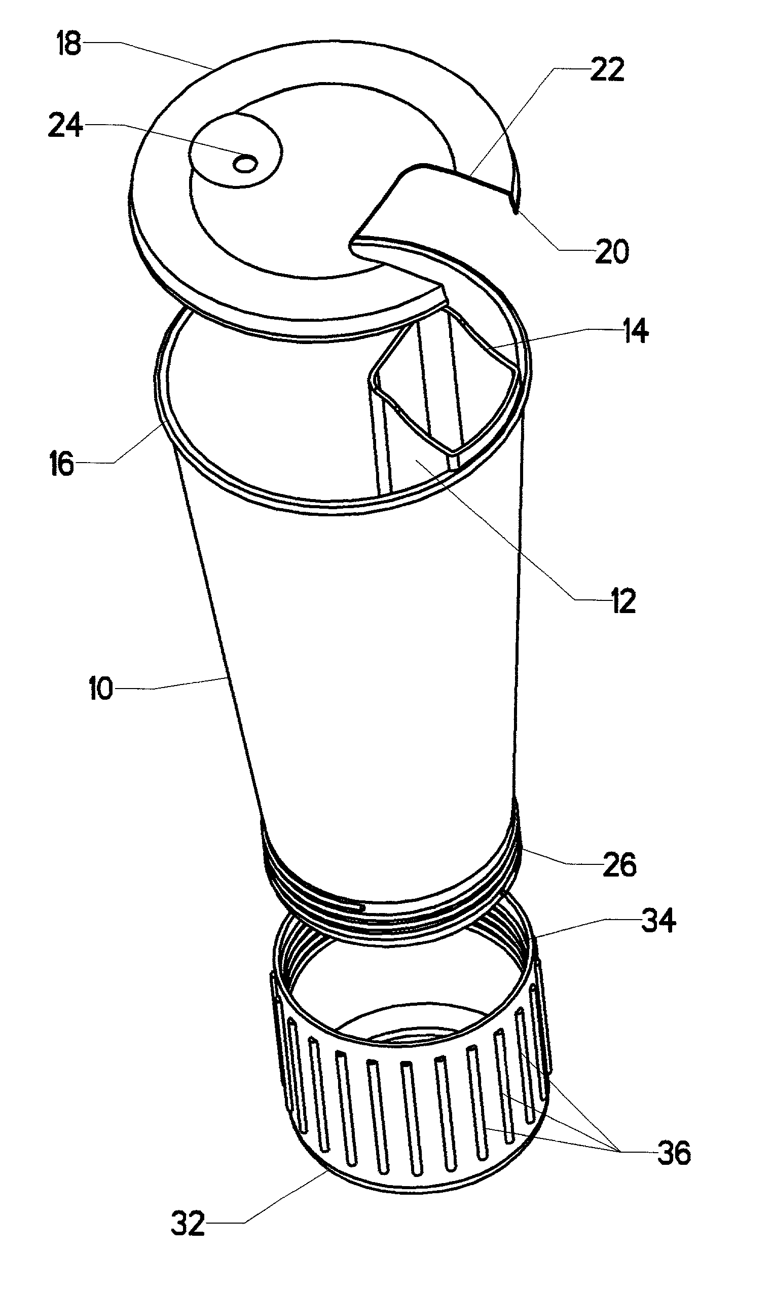
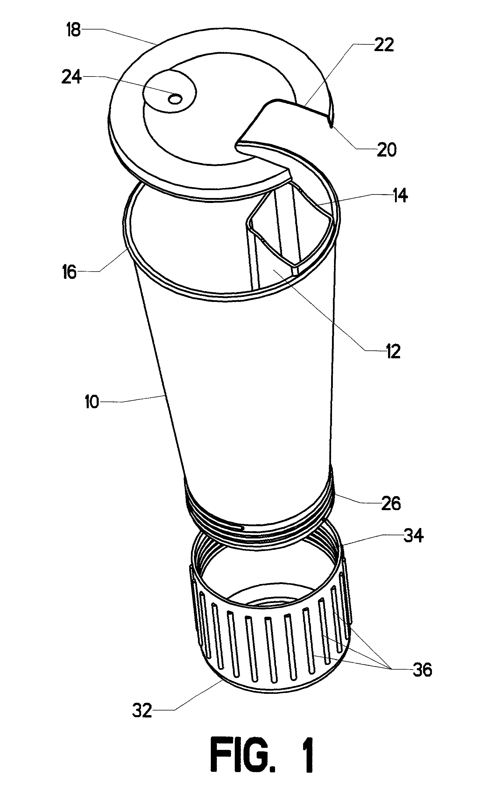
[0040]FIG. 1 depicts the components of the invention in a disassembled (exploded) state. The central component is cup body 10. Cup body 10 could be formed in virtually any shape. However, as many cup holders are designed to accommodate cylindrical objects, it is advantageous to create cup body 10 as a tapered cylinder. Its interior is hollow, so that it can contain the desired beverage. Its upper portion is open. Turning briefly to FIG. 2, the reader will observe that its lower portion is sealed by bulkhead 28.

[0041]Returning now to FIG. 1, the reader will observe that cup body 10 further includes saliva conduit 12. Saliva conduit 12 runs vertically from the upper portion of cup body 10 down to bulkhead 28. The upper portion of cup body 10 is formed into lip 16, which runs completely around the perimeter. The upper portion of saliva conduit 12 actually extends above lip 16 to form mouthpiece 14. Saliva conduit 12 is sealed off from the interior of cup body 10. Turning back to FIG. 2...


PUM


Abstract

A beverage cup having a detachable saliva reservoir so that a user may enjoy a beverage and smokeless tobacco products simultaneously. The cup has a saliva conduit running from its upper extremity down to a saliva reservoir which screws on the bottom. The upper portion of the conduit is formed into a mouthpiece which allows the user to easily deposit the saliva without the risk of it contaminating the contents of the cup. The beverage within the cup and the saliva reservoir are separated by an internal bulkhead. Cleaning is facilitated by the fact that the reservoir screws off the bottom. Both the cup and the reservoir can then be placed in a dishwasher or washed by hand.

Description

CROSS-REFERENCES TO RELATED APPLICATIONS[0001]Not ApplicableSTATEMENT REGARDING FEDERALLY SPONSORED RESEARCH OR DEVELOPMENT[0002]Not ApplicableMICROFICHE APPENDIX[0003]Not ApplicableBACKGROUND OF THE INVENTION[0004]1. Field of the Invention[0005]This invention relates to the field of drinking vessels. More specifically, the invention comprises a drinking cup with an integral saliva conduit and reservoir, so that a user who is dipping tobacco (snuff) may use a single vessel to hold a liquid drink and hold the saliva which must be spit out of the user's mouth.[0006]2. Description of the Related Art[0007]Many persons enjoy the use of smokeless tobacco products. One method of using such a product is to place a small portion of tobacco between the teeth and gums—commonly referred to as “dipping.” The presence of the tobacco causes the user to salivate. This saliva intermingles with the tobacco and can cause sickness if swallowed. Thus, the smokeless tobacco user commonly spits out the in...

Claims


Application Information

Patent Timeline
Patent Type & Authority Patents(United States)
IPC IPC(8): B65D77/00A47G19/22
CPCA47G19/22
Inventor WILSON, CHRISTOPHER A.
Owner WILSON CHRISTOPHER A
Why Eureka
Try Eureka