Thermal contact-bonding method and thermal contact-bonding apparatus

a contact bonding method and contact bonding technology, applied in the direction of mechanical control devices, process and machine control, instruments, etc., can solve problems such as product failure, and achieve the effect of preventing contamination

Inactive Publication Date: 2005-03-17
CANON KK
View PDF14 Cites 29 Cited by
  • Summary
  • Abstract
  • Description
  • Claims
  • Application Information

AI Technical Summary

Benefits of technology

[0039] The thermal contact-bonding apparatus can easily prevent contamination on a surface of a hot plate from adhering to a resin sheet by only providing a sucking control means in an upper chamber of a known thermal contact-bonding apparatus.
[0040] According to the present invention as a means for solving the above problems, it is necessary to separate at least a part of a surface of a hot plate from a resin sheet, and a depressed portion may be provided at least a part of the surface of the hot plate. For example, a depressed portion may be formed in an area on the surface of the hot plate to be in contact with a print paint printed on a back surface of the above-mentioned photovoltaic device. Thus, the printing area on the back surface of a material to be processed is not in contact with the surface of the hot plate, and the print paint does not adhere to the hot plate. Contaminant, dust, or the like easily deposits in the depressed portion. However, the surface of the hot plate and the resin sheet are separated at the depressed portion when the material to be processed is not charged, to thereby prevent adhering of the contaminant, dust, or the like to the material to be processed via the resin sheet.

Problems solved by technology

That is, the thermal contact-bonding method can prevent contaminant or the like deposited or adhered on the surface of the hot plate from adhering to the resin sheet which brought into direct contact with a surface of the material to be processed, and prevent the contaminant from again adhering to the surface of the material to be processed after the material to be processed is carried into the thermal contact-bonding apparatus for a thermal contact-bonding process, which causes product failure.

Method used


Image

  • Thermal contact-bonding method and thermal contact-bonding apparatus
  • Thermal contact-bonding method and thermal contact-bonding apparatus
  • Thermal contact-bonding method and thermal contact-bonding apparatus

Examples


embodiment 1

[0048] Embodiment 1

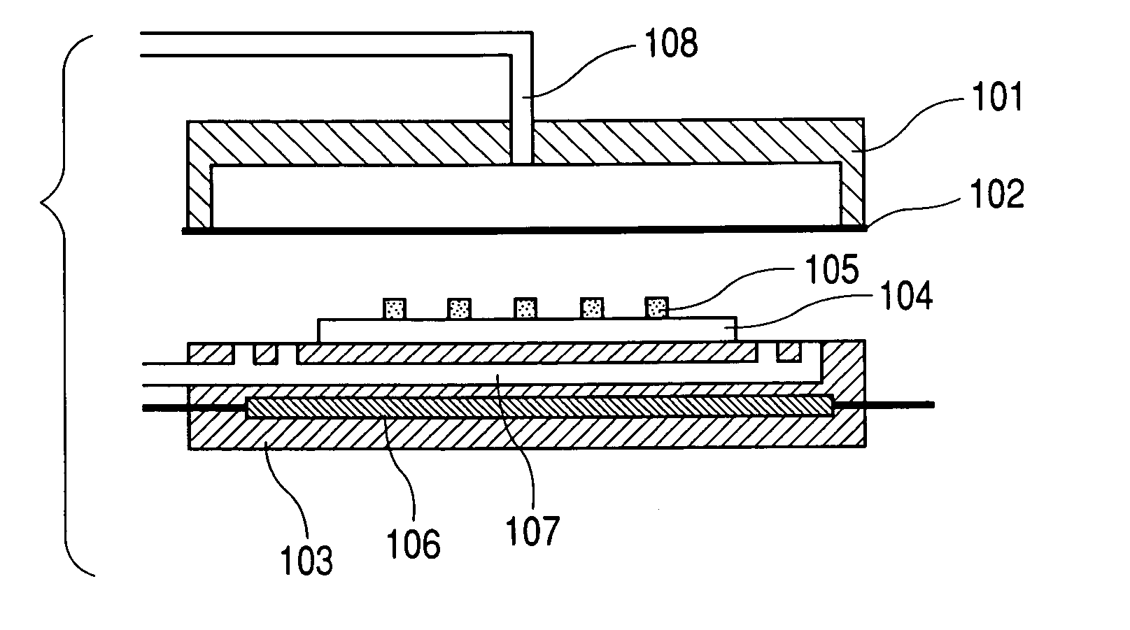
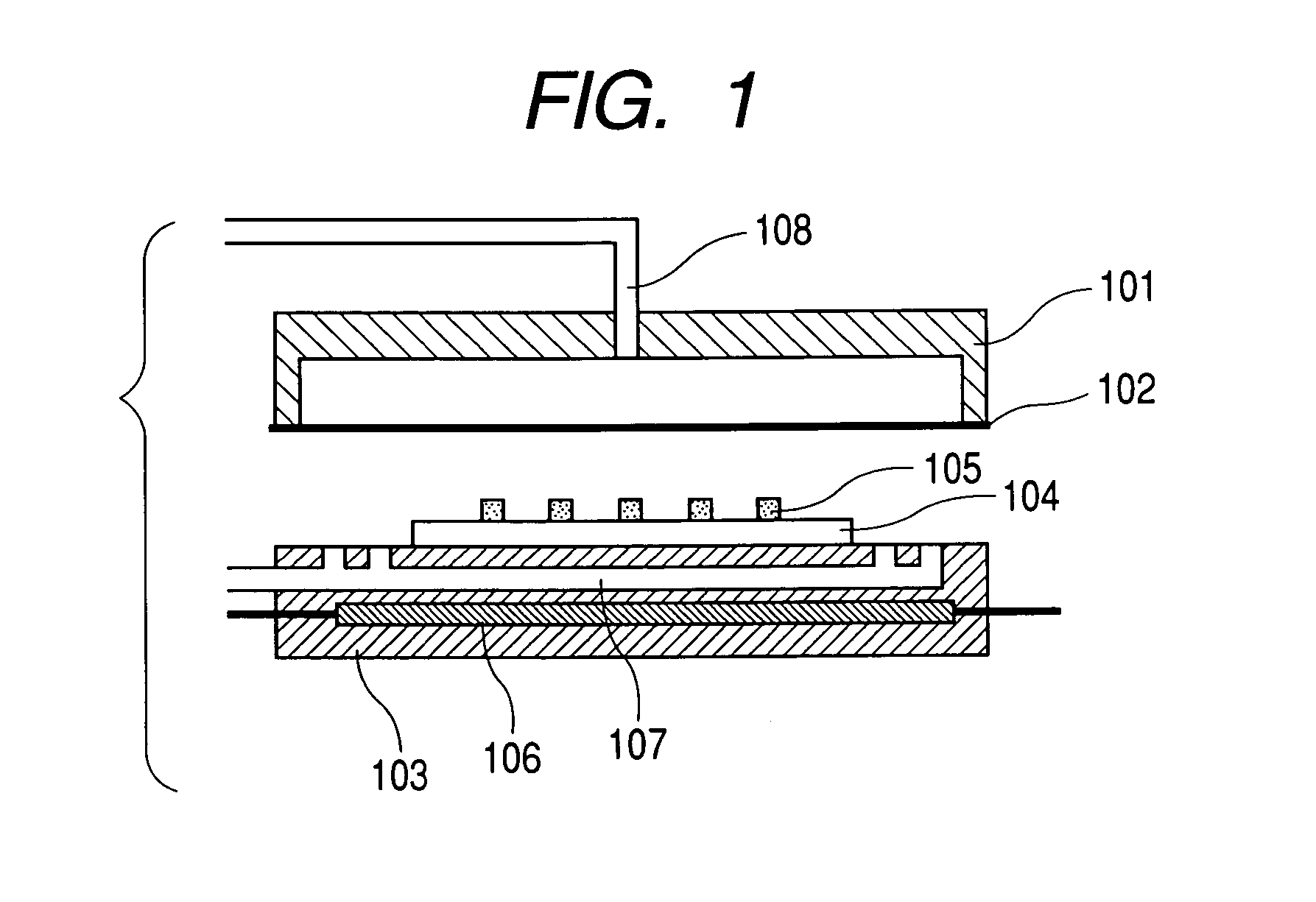
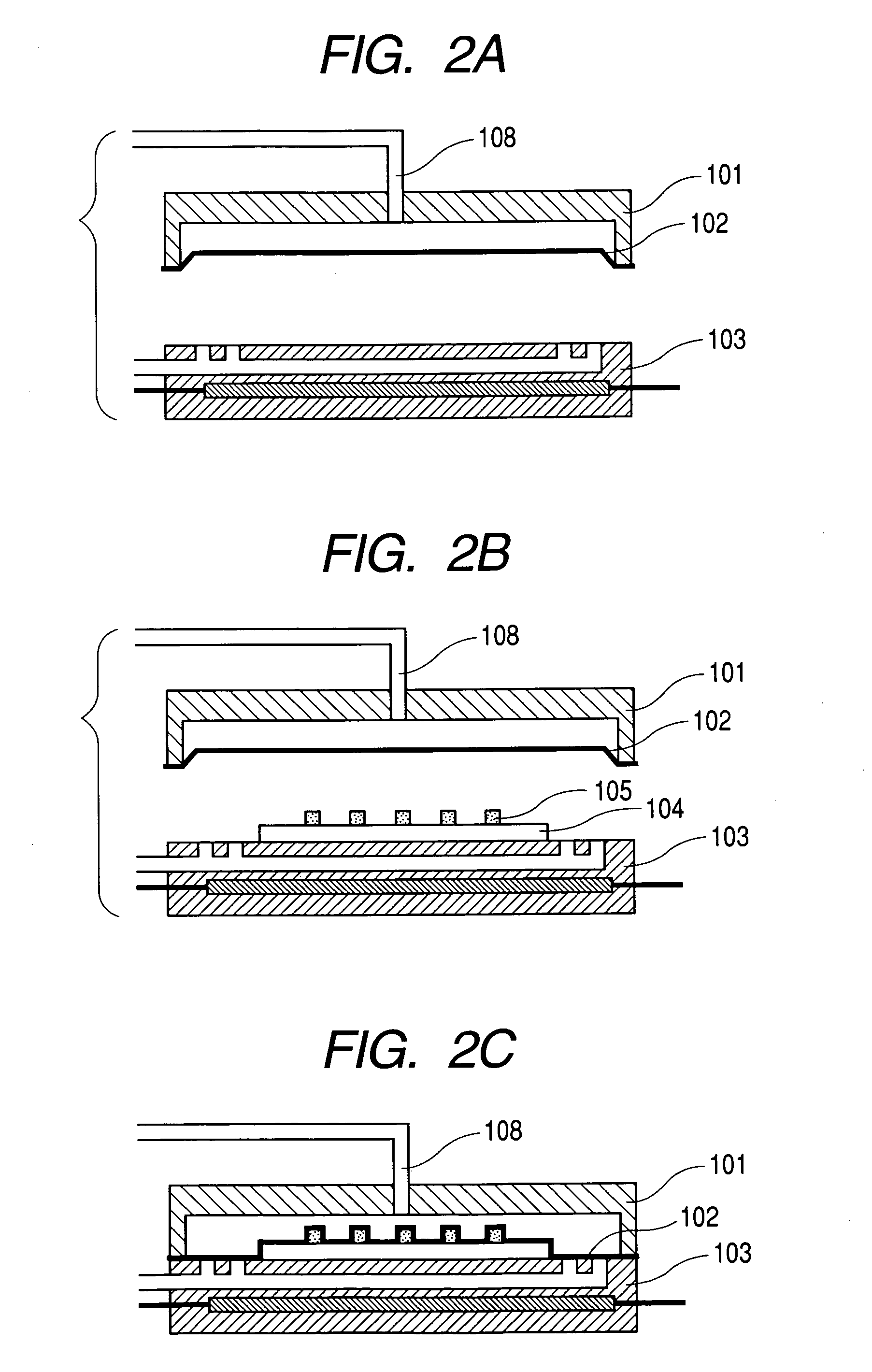
[0049]FIG. 1 and FIGS. 2A to 2F are schematic sectional view illustrating a thermal contact-bonding apparatus and a thermal contact-bonding method according to Embodiment 1. Embodiment 1 relates to a thermal contact-bonding method of arranging a conductive adhesive-coated metal wire as disclosed in U.S. Pat. No. 4,260,429 on a light-receiving surface of a photovoltaic device, and heating and pressing the whole with a heater, to thereby fix the metal wire on the light-receiving surface of the photovoltaic device.

[0050] In FIG. 1, an upper chamber 101 is provided with a depressed portion (400 mm×400 mm×depth of 5 mm) at a lower portion of the upper chamber. A resin sheet 102 is composed of a glass fabric sheet impregnated with 55 parts by weight of a polytetrafluoroethylene (PTFE) resin and a polytetrafluoroethylene (PTFE) resin tape attached to the central portion (380 mm×380 mm), which a material to be processed is brought into contact with, of the sheet. The res...

embodiment 2

[0063] Embodiment 2

[0064]FIG. 3 shows a schematic sectional view illustrating a material to be processed according to Embodiment 2, and FIG. 4 shows a schematic sectional view illustrating a thermal contact-bonding method according to Embodiment 2. Embodiment 2 relates to a coating method using a single vacuum laminator for producing a photovoltaic device module as disclosed in Japanese Patent Application Laid-Open No. H09-191116.

[0065] In FIG. 3, a photovoltaic device module is obtained by laminating a photovoltaic device 321; a glass fiber nonwoven fabric 322 (coating weight: 20 g / m2, thickness: 100 μm, acrylic resin binder content: 4.0 wt. %) as a light-receiving surface coating material; an EVA sheet 323 (thickness: 460 μm); an undrawn ETFE film 324 (thickness: 50 μm); an insulating film 326 (thickness: 75 μm) as a back surface coating material; EVA sheets 325 and 327 which are the same as that of used for the surface coating material 323 as adhesives; and Galvalume steel plate...


PUM

PropertyMeasurementUnit
thicknessaaaaaaaaaa
thicknessaaaaaaaaaa
widthaaaaaaaaaa

Abstract

The method of the present invention is a thermal contact-bonding method employing a thermal contact-bonding apparatus including at least a hot plate, an upper chamber, and a resin sheet provided at a lower portion of the upper chamber, the method including the steps of: pressing the upper chamber against the hot plate, while at least a part of a surface of the hot plate is separated from the resin sheet, to be in a stand-by state of the thermal contact-bonding apparatus, for a time of not charging a material to be processed; charging the material to be processed between the resin sheet and the hot plate; and subjecting the material to be processed to a thermal contact-bonding processing by making a space between the resin sheet and the hot plate under a vacuum state. Thus, the present invention provides a method and an apparatus for thermally contact-bonding a surface of the material to be processed in a clean state.

Description

BACKGROUND OF THE INVENTION [0001] 1. Field of the Invention [0002] The present invention relates to a thermal contact-bonding apparatus such as a vacuum press, a vacuum hot press, or a double vacuum apparatus. The present invention more specifically relates to a method and an apparatus for thermally contact-bonding a surface of a material to be processed which is brought into contact with a resin sheet in a clean state. [0003] 2. Related Background Art [0004] A thermal contact-bonding apparatus such as a vacuum press, a vacuum hot press, or a double vacuum apparatus is suitably used for laminate molding of an outer surface of a molded substrate having a three-dimensional shape including a cabinet for audio or visual equipment, furniture, and a container by bonding a decorative sheet such as a transfer sheet or an adhesive sheet along the outer surface of such a molded substrate, for example, for surface finishing such as decoration. [0005] For example, as a method of bonding and la...

Claims


Application Information

Patent Timeline
Patent Type & Authority Applications(United States)
IPC IPC(8): B29L9/00B29C65/48B29L31/34H01L31/04H01L31/18
CPCB32B37/10B32B37/1009Y10T156/1028H01L31/18B32B2457/12
Inventor TAKEYAMA, YOSHIFUMI
Owner CANON KK
Why Eureka
Try Eureka