Energy absorption impact system and method for vehicle bumpers and the like

a technology of energy absorption and impact system, which is applied in the direction of bumpers, roofs, vehicular safety arrangements, etc., can solve the problems of high manufacturing cost, large profile unsuitable for compact bumper designs, and high manufacturing cost, and achieves different energy absorption characteristics, low cost, and easy adaptation

Inactive Publication Date: 2006-06-27
BENTELER AUTOMOTIVE CORP
View PDF12 Cites 41 Cited by
  • Summary
  • Abstract
  • Description
  • Claims
  • Application Information

AI Technical Summary

Benefits of technology

[0008]Another aspect of the present invention provides an energy absorption impact system that is particularly adapted for high speed crashes and side hit collisions. The mounting plate serves to direct the deformation of the crush box during energy absorption. The tapered construction of the crush member provides a very simple, low cost design that can be readily adapted for a wide variety of different applications by simply varying the thickness of the walls and / or the degree of taper or draft of the walls relative to the mounting plate. Furthermore, the size and thickness of the mounting plate can be readily varied to achieve different energy absorption characteristics. The energy absorbing impact system is relatively lightweight, can be inexpensively manufactured, and has a very compact design that can be used in narrow bumper applications.

Problems solved by technology

However, many of such prior devices include certain shortcomings, including inconsistency in deformation and resultant energy absorption, instability in lateral loading, high manufacturing costs, post impact damage visibility, and large profiles unsuitable for compact bumper designs.
Also, while some of these prior bumper systems are relatively effective in absorbing the energy associated with a front end collision, they are not equally effective with side hits or collisions of the type having a significant side component, particularly for high speed crashes.

Method used


Image

  • Energy absorption impact system and method for vehicle bumpers and the like
  • Energy absorption impact system and method for vehicle bumpers and the like
  • Energy absorption impact system and method for vehicle bumpers and the like

Examples


Embodiment Construction

[0028]For purposes of description herein the terms “upper”, “lower”, “right”, “left”, “rear”, “front”, “vertical”, “horizontal” and derivative thereof shall relate to the invention as installed on the front bumper of an associated vehicle. However, it is to be understood that the invention may assume various alternative orientations and step sequences, except where expressly specified to the contrary. It is also to be understood that the specific devices and processes illustrated in the attached drawings, and described in the following specification, are simply exemplary embodiments of the inventive concepts defined in the appended claims. Hence, specific dimensions and other physical characteristics relating to the embodiments disclosed herein are not to be considered as limiting, unless the claims expressly state otherwise.

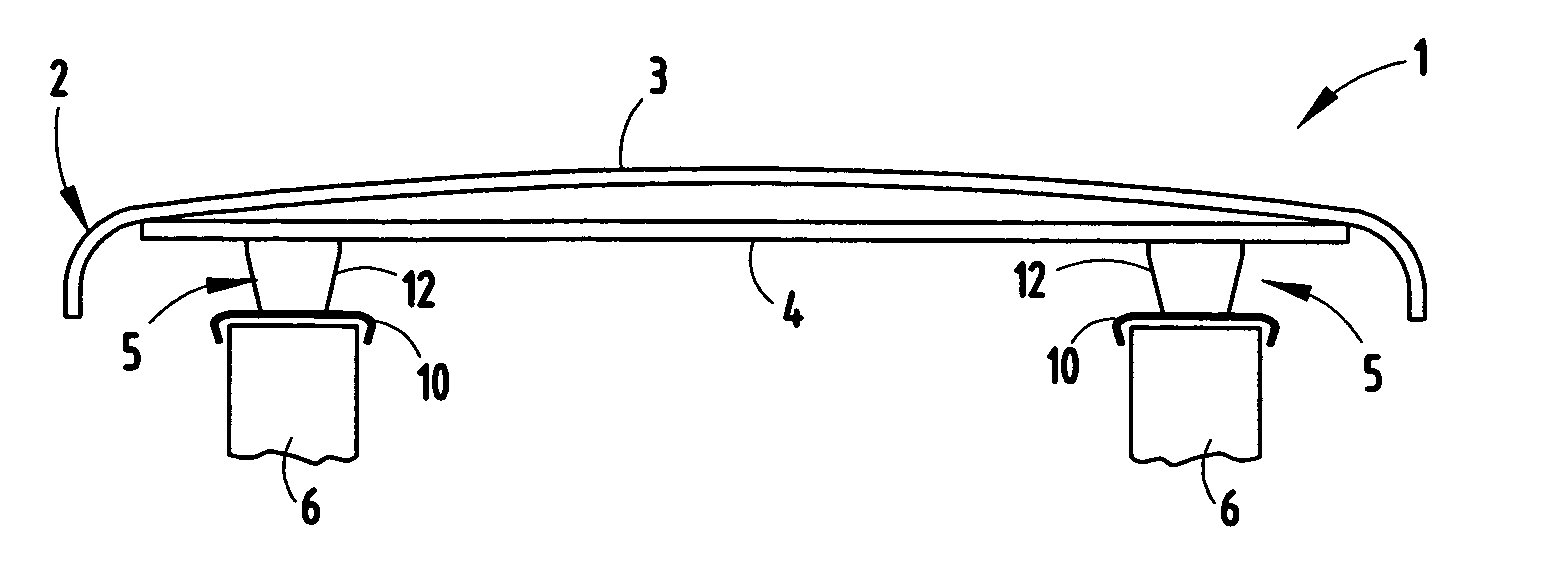
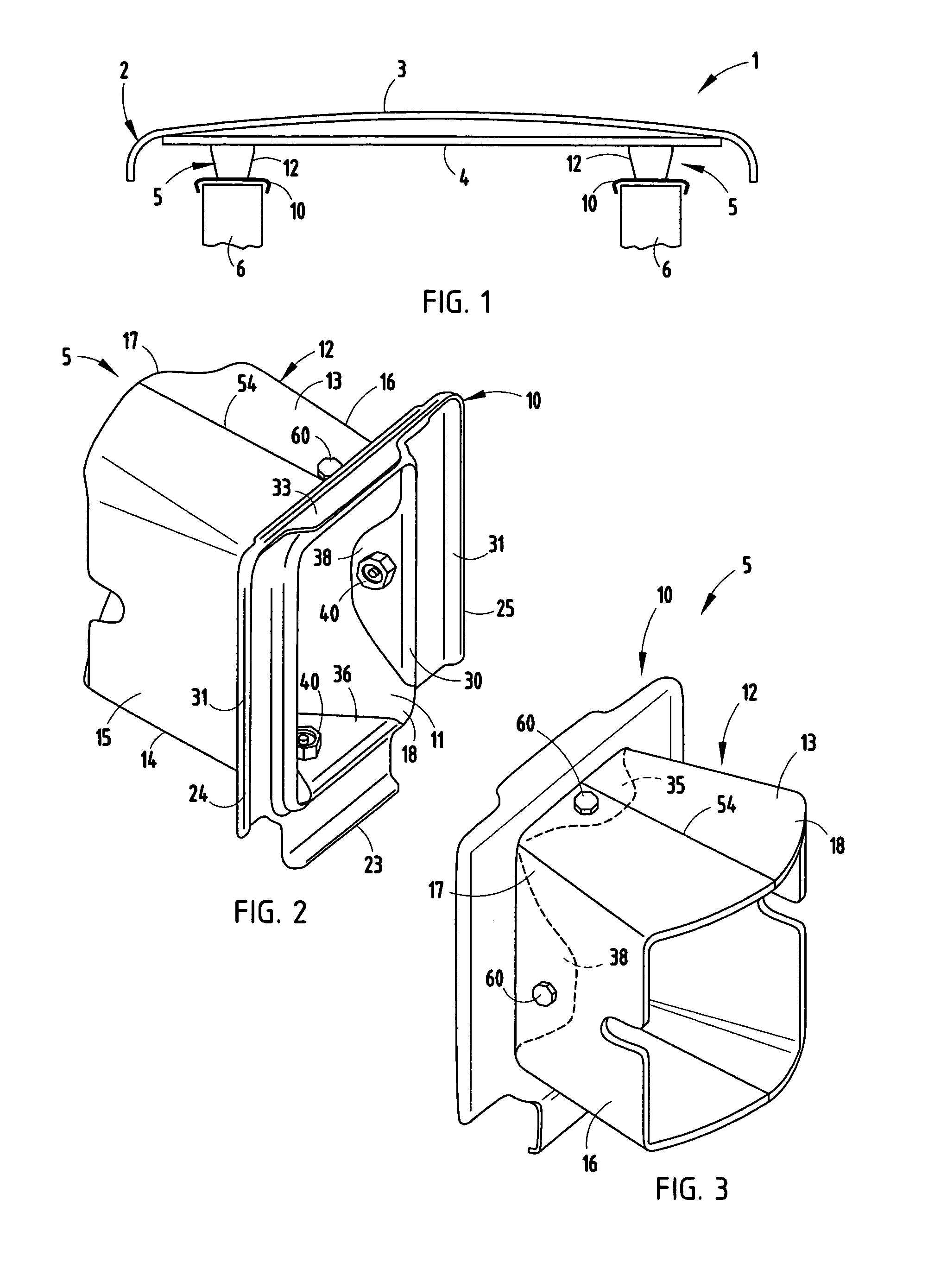
[0029]The reference numeral 1 (FIG. 1) generally designates an energy absorption impact system or apparatus embodying the present invention, which is particular...


PUM


Abstract

An energy absorption impact system for vehicle bumpers and the like includes a mounting plate with a central opening therethrough, and a generally box-shaped sheet metal crush member. The crush member has a top wall, a bottom wall and opposite sidewalls arranged in a generally frustro-pyramidal shape, defining a large end connected with a vehicle bumper, and a small end connected with the mounting plate about the central opening. Impact on the vehicle bumper inelastically deforms the walls of the crush member toward the central opening in the mounting plate to absorb energy associated with the impact.

Description

BACKGROUND OF THE INVENTION[0001]The present invention relates to impact absorbing devices, and in particular to an energy absorbing impact system and method for vehicle bumpers and the like.[0002]Typical automotive bumper systems include three basic components. The first component is a decorative fascia, usually constructed of plastic or the like. The second component is a rigid impact beam, typically constructed of roll formed or stamped steel, which supports the decorative fascia. The third element is an energy absorption unit or assembly that operably connects the impact beam to the frame rails of an associated vehicle. These three components are designed to meet the performance requirements for both low and high speed impacts.[0003]It is beneficial to design the bumper system in such a way that limited damage is transferred to the vehicle frame rails under impact. One guideline provided for this design process is for the bumper system to have a peak loading capability equivalen...

Claims


Application Information

Patent Timeline
Patent Type & Authority Patents(United States)
IPC IPC(8): B60R19/34
CPCB60R19/34
Inventor KOLLARITSCH, JOSEPH C.BLUST, JASONDAGBA, ATALOLO
Owner BENTELER AUTOMOTIVE CORP
Why Eureka
Try Eureka