Clock control in sequential circuit for low-power operation and circuit conversion to low-power sequential circuit
a technology of low-power operation and sequential circuit, which is applied in the direction of generating/distributing signals, digital storage, instruments, etc., can solve the problems of complicated clock control of sequential circuit, and achieve the effect of reducing the overcrowding of signal lines
- Summary
- Abstract
- Description
- Claims
- Application Information
AI Technical Summary
Benefits of technology
Problems solved by technology
Method used
Image

Examples
embodiment 1
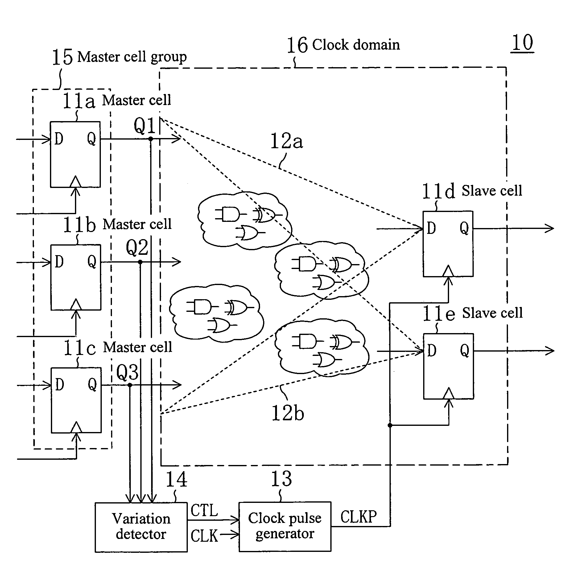
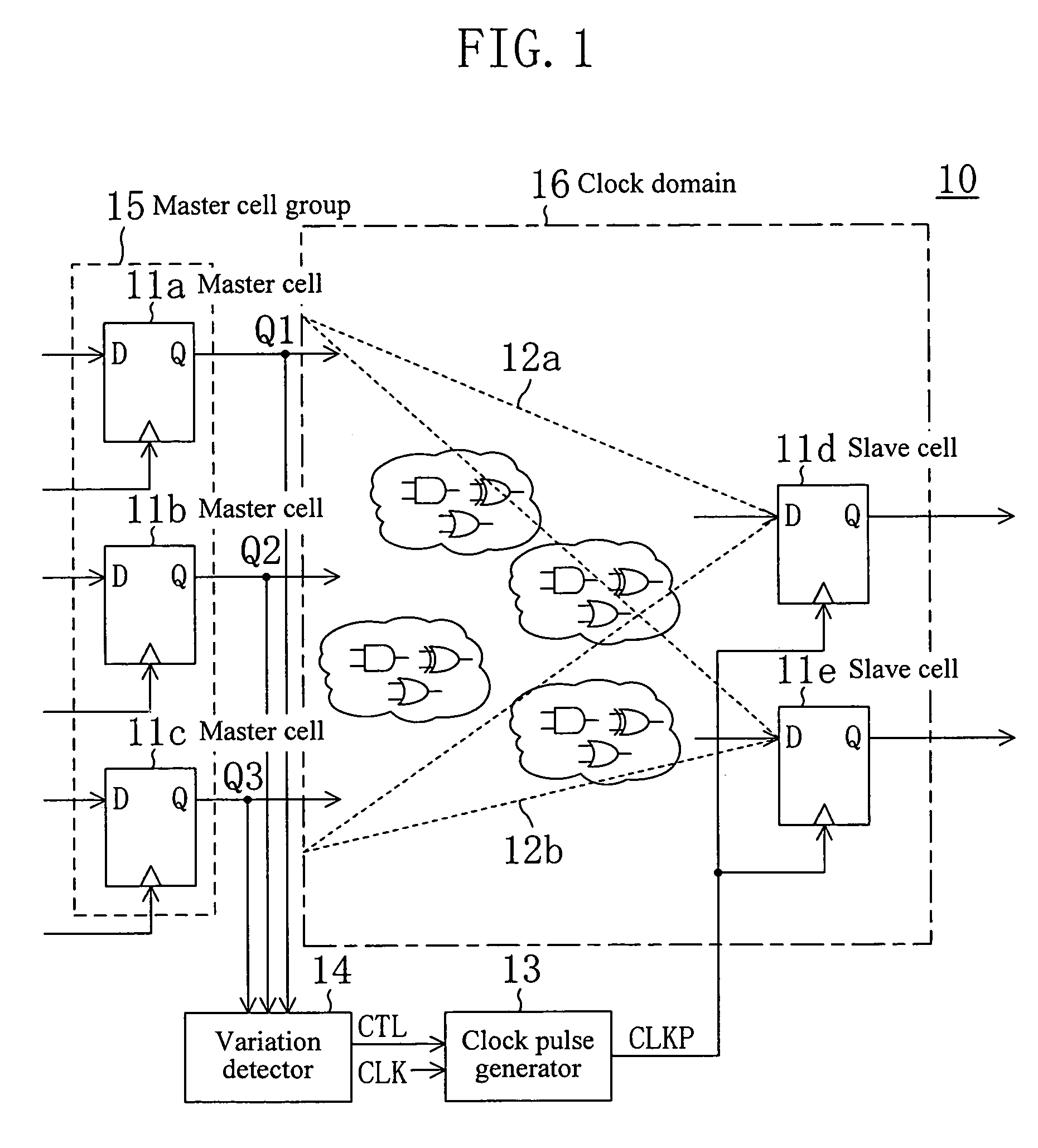
[0069]FIG. 1 illustrates a circuit structure of a sequential circuit according to embodiment 1 of the present invention. The sequential circuit 10 of embodiment 1 includes memory elements 11a, 11b, 11c, 11d and 11e (hereinafter, these are generically referred to as “memory elements 11”). Any of the memory elements 11 is selected as a master cell, and a memory element 11 whose content is varied according to a variation in the content of the master cell is referred to as a slave cell. The sequential circuit 10 further includes combinational circuits 12a and 12b, a clock pulse generator 13 for generating clock pulse CLKP as a synchronous clock for the slave cell, and a variation detector 14 for detecting a variation in the content of the master cell.
[0070]Herein, for convenience of illustration, it is assumed that the sequential circuit 10 includes the five memory elements 11, three of them (memory elements 11a, 11b, and 11c) being slave cells and the remaining two (memory elements 11d...
embodiment 2
[0081]FIG. 3 shows a circuit structure of a sequential circuit according to embodiment 2 of the present invention. The sequential circuit 20 of embodiment 2 includes memory elements 21 each having a variation output in place of the memory elements 11 of the sequential circuit 10 of embodiment 1. From the variation output of each memory element 21, a variation signal indicating that the content of the memory element 21 has been changed is output. (The variation signal corresponds to an original variation signal of the present invention.) Hereinafter, the sequential circuit 20 is described as to only aspects different from the sequential circuit 10. In FIG. 3, like elements and signals are denoted by like reference numerals used in FIG. 1, and detailed descriptions for each of them are omitted.
[0082]The sequential circuit 20 includes a logic element 17 in place of the variation detector 14 described in embodiment 1. The logic element 17 receives variation signals M1, M2 and M3 output ...
embodiment 3
[0099]In the sequential circuits 10 and 20 of embodiments 1 and 2, if a plurality of master cells are included in a master cell group, the number of output signals Q and the number of variation signals M are increased, and accordingly, congestions are caused in the signal line for transmitting a variation occurred in the content of a master cell to a clock pulse generator. Embodiment 3 of the present invention realizes a circuit structure which avoids the overcrowding of signal lines.
[0100]A clock generation circuit of embodiment 3 is now described before the explanation of a sequential circuit of embodiment 3.
[0101]FIG. 9 shows a circuit structure of the clock generation circuit of embodiment 3. The clock generation circuit 22 includes a clock pulse generator 23 for generating clock pulse CLK and a clock pulse generation request signal line 25 for transmitting request signal CLKREQ which requests the clock pulse generator 23 to generate a clock pulse.
[0102]The clock pulse generatio...
PUM
 Abstract
Description
Claims
Application Information