
Thermal bubble type micro inertial sensor

Active Publication Date: 2006-07-04
XIANGQUN SCI & TECH
View PDF18 Cites 31 Cited by
  • Summary
  • Abstract
  • Description
  • Claims
  • Application Information

AI Technical Summary

Benefits of technology

[0009]An object of the invention is to provide a thermal bubble type micro inertial sensor serving as an inclinometer and an accelerometer to sense the variations of position, tilt and acceleration. The micro inertial sensor utilizes the property of liquid with a higher density acting as a virtual proof mass to push a thermal bubble, which is formed by heating the liquid to its vaporization point, to move. Inside the thermal bubble, the temperature is higher than that of the surrounding liquid and a clear junction formed thereat. So, the micro inertial sensor does not need any mechanical proof mass and advantageously has a quick response speed to overcome the drawbacks of the prior gas convective type.
[0010]Another object of the invention is to provide a structure, which includes a heater and a set of temperature-sensing members suspended above the substrate and formed by silicon micromachining technology that enhances the heating efficiency of the heater, the sensitivity of each temperature-sensing member, and thus the measurement capability of the micro inertial sensor.
[0011]Still another object of the invention is to provide a thermal bubble type micro inertial sensor, in which associated circuits are integrated on a single chip by silicon integrated circuit process technology. Thus, the cost of the sensor and the size of the sensor may be greatly reduced.

Problems solved by technology

However, since the conventional inertial sensor is bulky and expensive in price, it is limited in various applications.
However, the maximum drawback of such structures is that the fabrication yield rate is low and the elastically supported proof mass may be damaged by sticking effects or external shock forces.
However, since the heat transfer speed of the gas is slow, the response speed of this gas convective accelerometer is quite slow (about 30 Hz), which limits its application.
Moreover, since the accelerometer has to be packaged in a sealed chamber to control the environment pressure, the cost is greatly increased.

Method used


Image

  • Thermal bubble type micro inertial sensor
  • Thermal bubble type micro inertial sensor
  • Thermal bubble type micro inertial sensor

Examples


Embodiment Construction

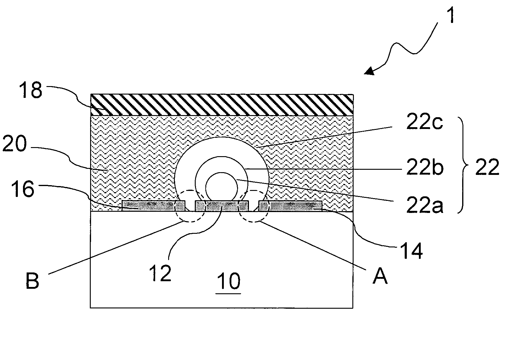
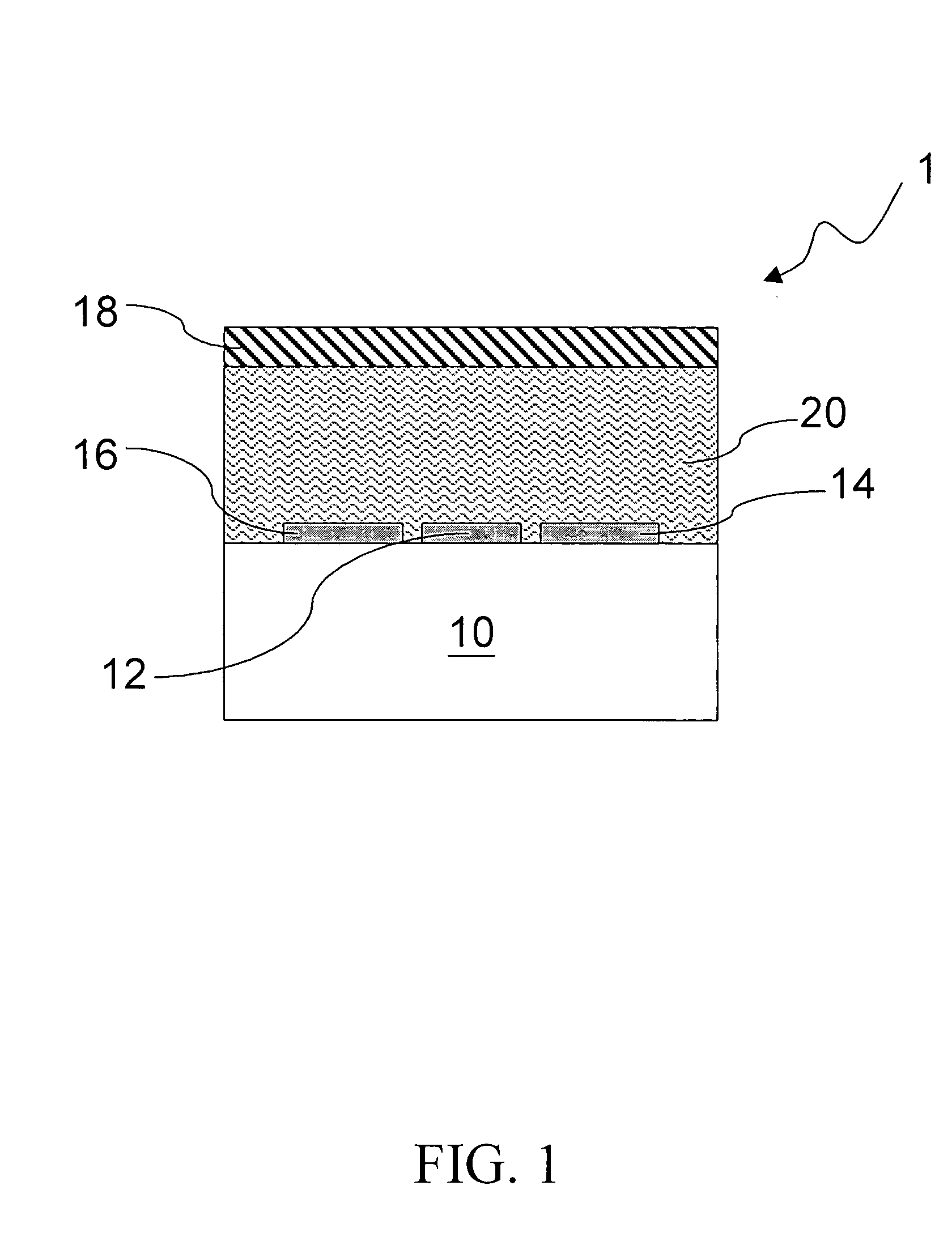
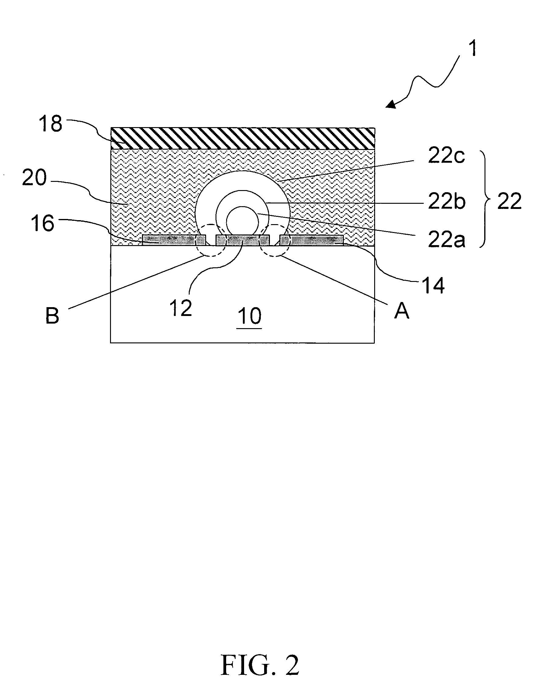
[0023]The operation principle of the thermal bubble type micro inertial sensor of the invention, which serves as an accelerometer (or micro-accelerometer) and an inclinometer will be described with reference to FIGS. 1 to 4. FIG. 1 is a cross-sectional view showing a structure of a thermal bubble type micro inertial sensor of the invention. Referring first to FIG. 1, the thermal bubble type micro inertial sensor 1 includes a substrate 10, a heater 12, temperature sensing members 14 and 16, a cap 18, and a liquid 20. The substrate 10 is typically a silicon substrate. The heater 12 is arranged on the substrate 10. The temperature sensing members 14 and 16 are symmetrically arranged on the substrate 10 and at opposite sides of the heater 12. The temperature sensing members 14 and 16 may sense the temperature difference beside the heater 12. The heater 12 and the temperature sensing members 14 and 16 may be formed of a metal material, such as platinum or tungsten, as well as a silicon o...


PUM


Abstract

A thermal bubble type micro inertial sensor formed by micromachining technology includes a substrate, a heater arranged on the substrate, four temperature sensing members, a cap arranged above the substrate to cover and encapsulate the heater and the temperature sensing members, and a liquid filled into a chamber formed between the cap and the substrate. The temperature sensing members are symmetrical arranged at opposite sides of the heater and on the substrate, respectively, to sense the temperature difference beside the heater. The heater heats and partially vaporizes the liquid to form a thermal bubble in the liquid environment. Controlling the liquid characteristics and heater temperature may control the bubble size and enable the temperature sensing members to sense the temperature distribution variation. The sensor may serve as an inclinometer to sense the tilt, as well as an accelerometer to measure the acceleration.

Description

[0001]This Nonprovisional application claims priority under 35 U.S.C. § 119(a) on Patent Application No(s). 091134748 filed in Taiwan on Nov. 29, 2002, the entire contents of which are hereby incorporated by reference.BACKGROUND OF THE INVENTION[0002]1. Field of the Invention[0003]The invention relates to a micro inertial sensor, and more particularly to a thermal bubble type micro inertial sensor serving as an inclinometer and an accelerometer for sensing variations of position, tilt, and acceleration.[0004]2. Description of the Related Art[0005]Conventional mechanical type inertial sensors, such as an accelerometer and a gyroscope, are indispensable devices for navigation control. However, since the conventional inertial sensor is bulky and expensive in price, it is limited in various applications. Micro inertial sensors based on MEMS (Micro-Electro-Mechanical-System) technology are recently studied and developed well for realistic product. Using the MEMS technology to manufacture...

Claims


Application Information

Patent Timeline
IPC IPC(8): G01P15/08G01P15/00G01C9/00G01P15/12G01P15/18
CPCG01C9/00G01P15/18G01P15/12G01P15/008
Inventor CHOU, BRUCE C. S.
Owner XIANGQUN SCI & TECH
Learn More