

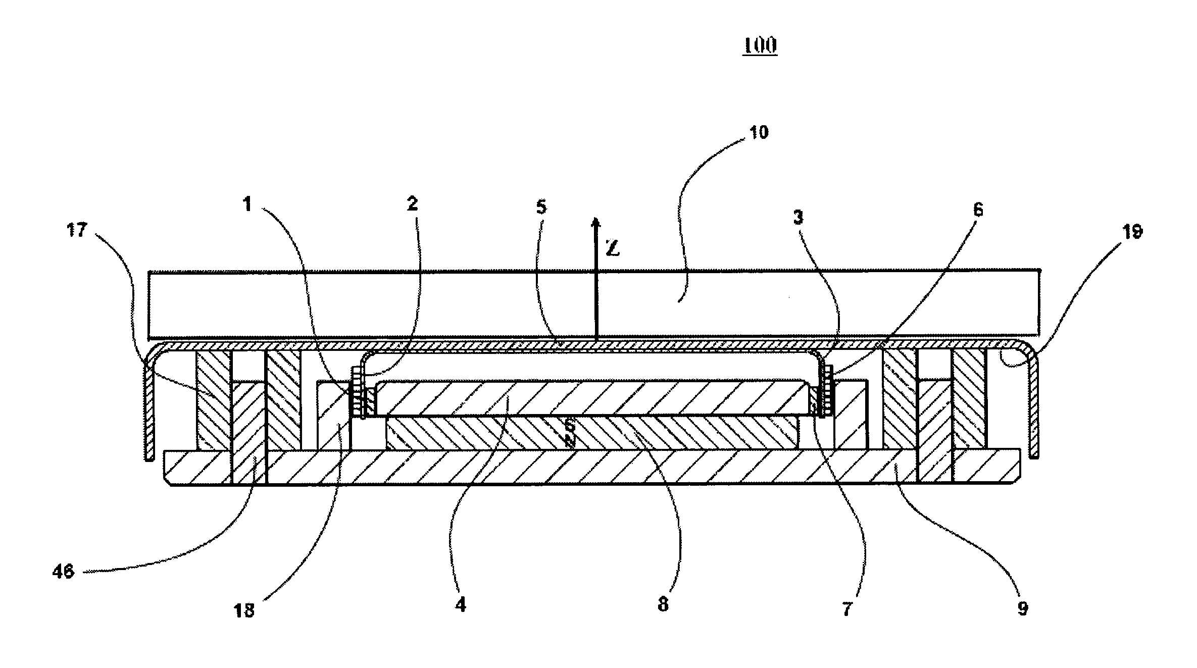
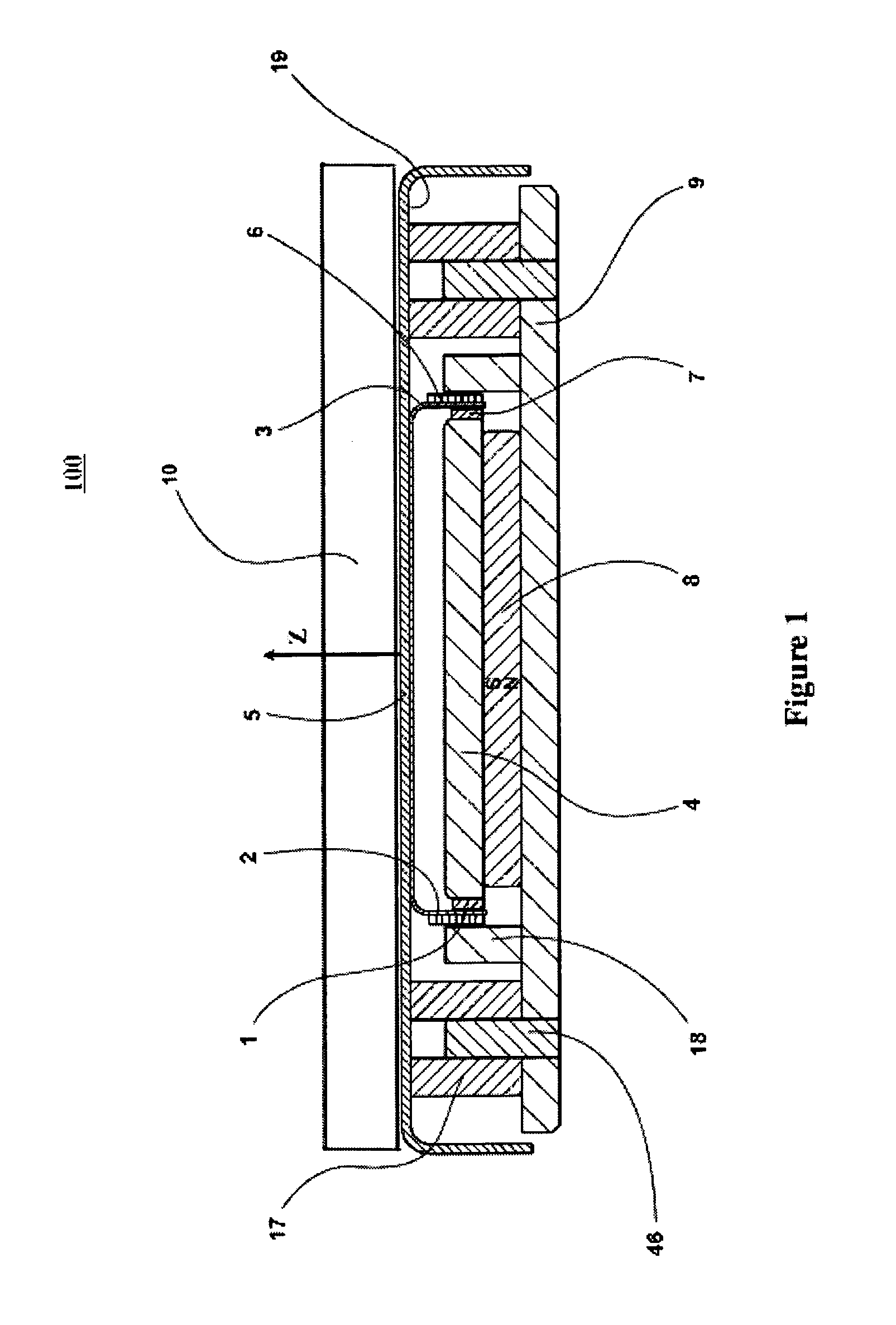
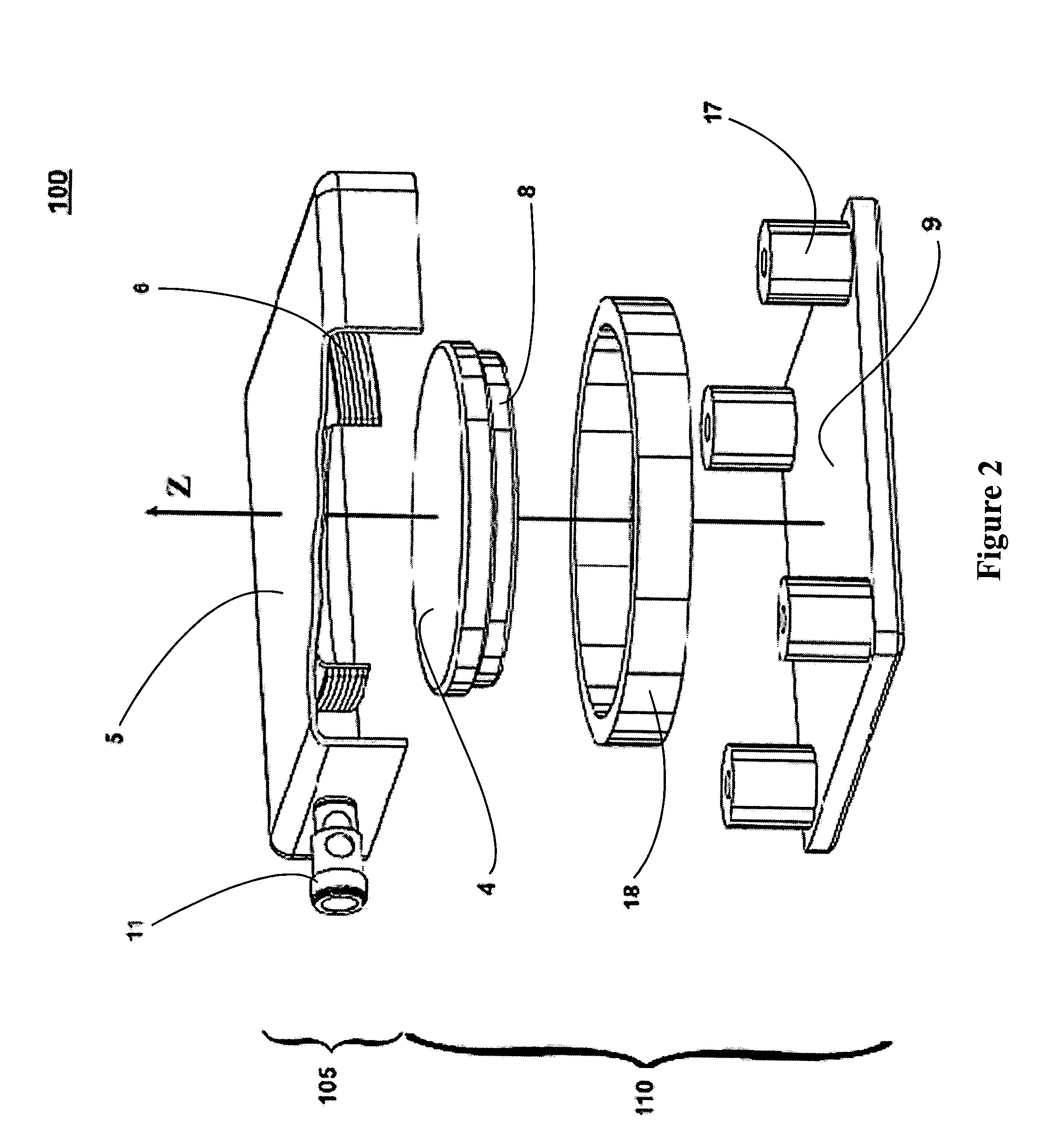
Robust low profile shaker
a shaker and low-profile technology, applied in the direction of chairs, magnetic bodies, instruments, etc., can solve the problem of insensitive assembly to moment-induced tilting, and achieve the effect of high efficiency
- Summary
- Abstract
- Description
- Claims
- Application Information
AI Technical Summary
Benefits of technology
Problems solved by technology
Method used
Image

Examples
Embodiment Construction
[0028]The present description is of the best presently contemplated mode of carrying out the invention. This description is made for the purpose of illustrating the general principles of the invention and should not be taken in a limiting sense.
[0029]All publications referenced herein are fully incorporated by reference as if fully set forth herein.
[0030]The present invention can find utility in a variety of implementations without departing from the scope and spirit of the invention, as will be apparent from an understanding of the principles that underlie the invention. For instance, the present invention is best described as used in conjunction with items of furniture and entertainment systems (including home audio / video equipment, theater or other large public venue equipment, demonstration, simulation, or game systems, etc) such that the shaker can vibrate the home furnishings in response to electrical signals from the entertainment system, however it may find utility when used...
PUM
 Abstract
Description
Claims
Application Information