
Sawdust collection system for a circular saw

a collection system and circular saw technology, applied in metal sawing devices, metal sawing accessories, manufacturing tools, etc., can solve the problems of inconvenient design and uneven thickness of workpieces

Inactive Publication Date: 2006-07-04
CHANG CHIN CHIN
View PDF7 Cites 30 Cited by
  • Summary
  • Abstract
  • Description
  • Claims
  • Application Information

AI Technical Summary

Benefits of technology

[0009]The main objective of the present invention is to provide an improved sawdust collection system for a circular saw, which can effectively collect sawdust during operating the circular saw.
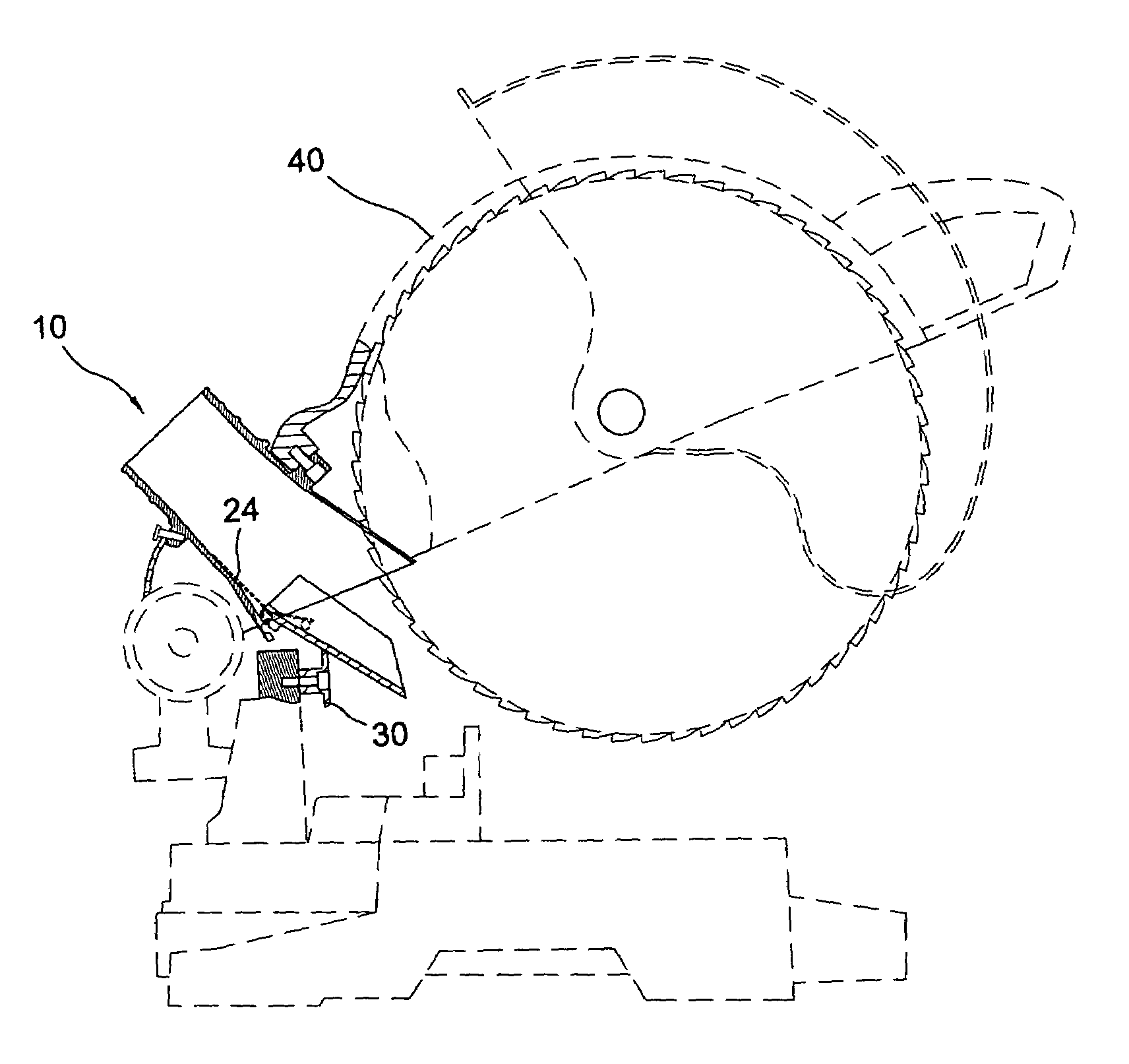
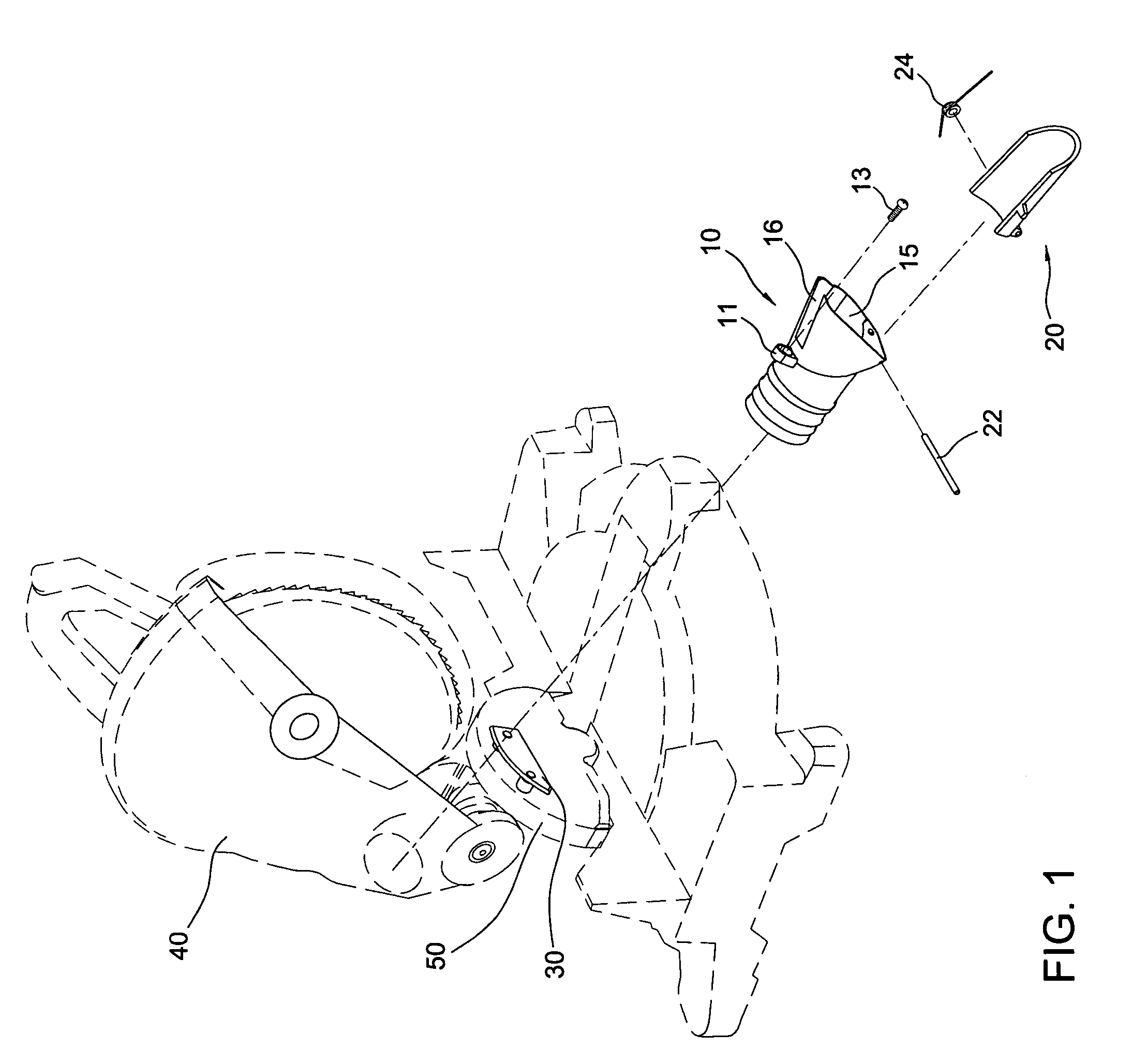
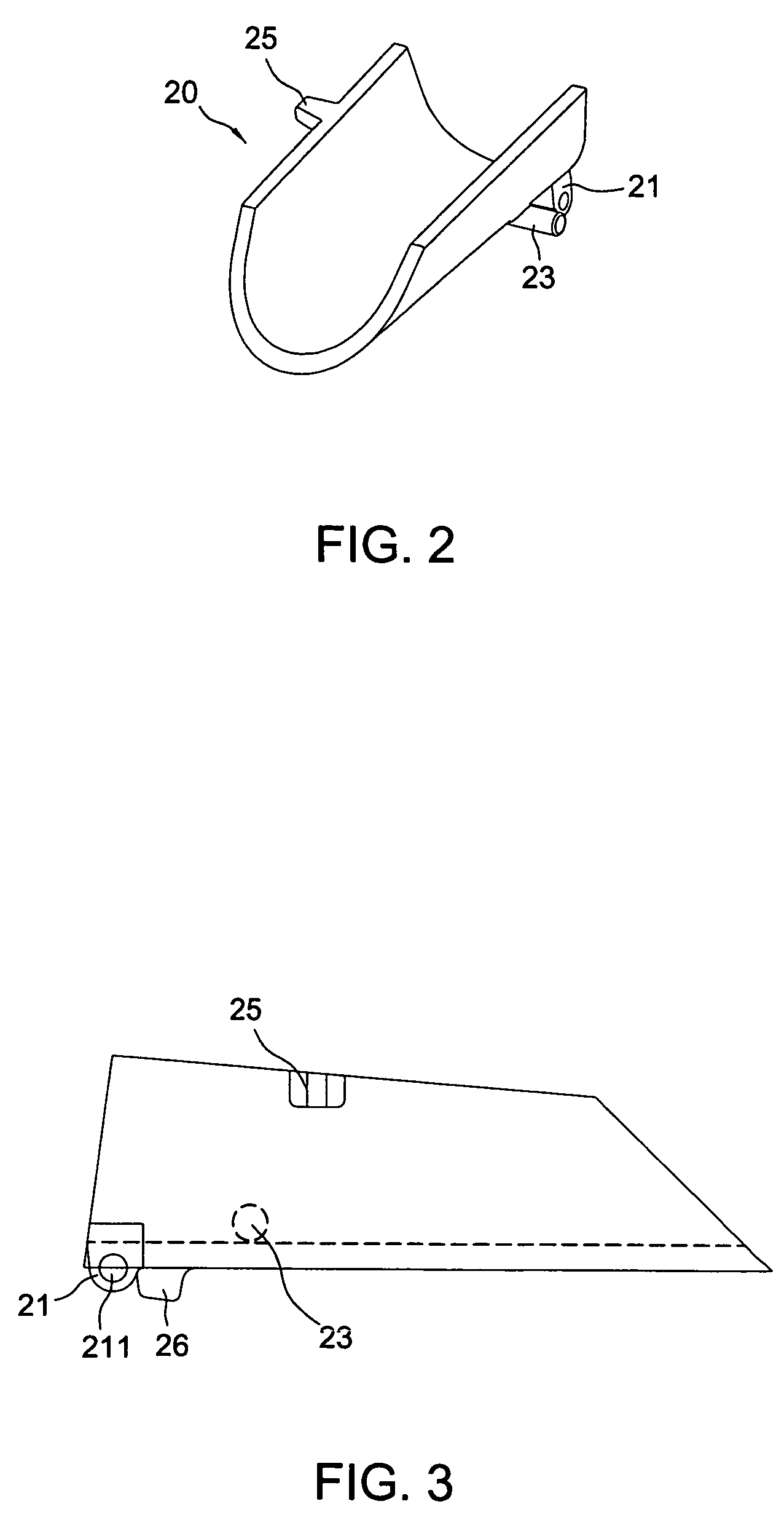
[0010]To achieve the objective, the sawdust collection system in accordance with the present invention comprises a sawdust duct longitudinally secured in a saw blade housing and having an enlarged portion formed on a front end of the sawdust duct. A sawdust chute is partially longitudinally received in a lower portion of the enlarged portion of the sawdust duct. A pin laterally extends the sawdust duct and the sawdust chute to pivotally mount the sawdust chute to the sawdust duct such that the sawdust chute can be swung relative to the sawdust duct. A first stopper laterally outwardly extends from a bottom of the sawdust chute and a torsion spring is sleeved on the pin. The torsion spring has a first end abutting against an inner periphery of the sawdust duct and a second end downward abutting against the first stopper to prevent the sawdust chute from a vibration during operating. A second stopper laterally outwardly extends from a top of the sawdust chute. The second stopper selectively abuts a distal edge of the enlarged portion to limit a moving range of the sawdust duct and prevent the sawdust chute from being contacted with the saw blade when the saw blade is downward moved near a base of the circular saw. A support is secured on a body of the circular saw for supporting a bottom of the sawdust chute to adjust the angle between the sawdust duct and the sawdust chute before the saw blade housing contacting with the second stopper.

Problems solved by technology

However, the thickness of the workpiece is not uniformed such that the operator needs to often adjust the angle between the guide pass and the guide tube due to the thickness of the workpiece during operating.
It is an inconvenient design.

Method used


Image

  • Sawdust collection system for a circular saw
  • Sawdust collection system for a circular saw
  • Sawdust collection system for a circular saw

Examples


Embodiment Construction

[0021]Referring to the drawings and initially to FIGS. 1–6, a sawdust collection system for a circular saw in accordance with the present invention comprises a sawdust duct (10) adapted to be longitudinally mounted in a saw blade housing (40) of the circular saw, a sawdust chute (20) pivotally mounted to a front end of the sawdust duct (10) and a support (30) adapted to be secured on a body (50) of the circular saw for selectively supporting a bottom of the sawdust chute (20).

[0022]The sawdust duct (10) includes a first ear (11) and a second ear (12) respectively extending from an outer periphery of the sawdust duct (10) and diametrically corresponding to each other. A through hole (not numbered) is defined in the first ear (11) and the threaded hole (not numbered) is defined in the second ear (12). A first bolt (13) extends through the through hole and is screwed into the saw blade housing (40), and a second bolt (14) extends through the saw blade housing (40) and is screwed into t...


PUM

PropertyMeasurementUnit
angleaaaaaaaaaa
distanceaaaaaaaaaa
thicknessaaaaaaaaaa

Abstract

A sawdust collection system includes a sawdust duct secured in a saw blade housing and having an enlarged portion formed on a front end thereof. A sawdust chute is partially pivotally received in a lower portion of the enlarged portion of the sawdust duct such that the sawdust chute can be swung relative to the sawdust duct. A first stopper laterally outwardly extends from a bottom of the sawdust chute and a torsion spring is mounted between the sawdust duct and the sawdust chute to prevent the sawdust chute from a vibration during operating. A second stopper laterally outwardly extends from a top of the sawdust chute. The second stopper selectively abuts a distal edge of the enlarged portion for limiting the moving range of the sawdust duct.

Description

BACKGROUND OF THE INVENTION[0001]1. Field of the Invention[0002]The present invention relates to a sawdust collection system, and more particularly to a sawdust collection system for a circular saw.[0003]2. Description of Related Art[0004]As well know, a sawdust collection system is widely used to a circular saw for collecting sawing sawdust during operating the circular saw.[0005]As regard to U.S. Pat. No. 5,819,619, Philip discloses a sawdust collection system for compound meter saw including a sawdust duct pivotally moved with the saw blade. The sawdust duct only contains a sawdust-receiving opening in its forward end for guiding sawdust thereinto. For preventing the saw blade from breaking the sawdust duct, a certain distance is arranged between the sawdust-receiving opening and the sawing edge of the saw blade. As a result, the sawdust collecting effect is reduced.[0006]As regard to U.S. Pat. No. 5,927,171, Katsuhiko discloses a bench circular saw machine including a guide tube...

Claims


Application Information

Patent Timeline
Patent Type & Authority Patents(United States)
IPC IPC(8): B23D45/04
CPCB23D59/006Y10T83/207Y10T83/7697Y10T83/7788Y10T83/8773
Inventor CHANG, CHIN-CHIN
Owner CHANG CHIN CHIN
Learn More