Method and arrangement for controlling the temperature of the outstream flow from a heat exchanger and measuring produced heat

a technology of heat exchanger and temperature, which is applied in the direction of temperatue control, domestic heating details, electrical means, etc., can solve the problems of easy oscillation in control, risk of scalding, and inability to optimise statically programmed characteristics of the regulator with respect to all occurring operation scenarios, so as to reduce the time required

Inactive Publication Date: 2006-07-04
LINDGREN
View PDF17 Cites 28 Cited by
  • Summary
  • Abstract
  • Description
  • Claims
  • Application Information

AI Technical Summary

Benefits of technology

[0018]The invention provides improved load adaptability, independent of consumer size. Also, the risk for calcification in heat exchangers is reduced significantly, since faster control systems with higher precision can counter temperature peaks above 60° C.
[0019]Consistency of the hot tap water temperature on the consumer side is based upon determination of the needed heating power needed to increase (alternatively, in a cooling application, to reduce) the temperature of the secondary flow to a set point value. The invention is not based upon a dynamic correction of the error between the desired and the actual temperature of the outbound secondary medium, which entails that the control may be executed without feedback of the actual temperature value from the secondary side.
[0020]In most district heating systems, the invention also entails that the control system may be installed without adjustment of regulatory parameters, which strongly reduces the time required for installation and service / fine tuning.
[0021]In a further embodiment, the procedure and the device are suitable also to be able to deal with changes on the secondary side, concerning temperature fluctuations of the inbound water to be heated in the heat exchanger. This embodiment is applied when the temperature of the inbound cold water fluctuates. (In the normal case, the water is assumed to have a largely constant temperature.) Through this embodiment, the same system may be applied in a greater geographical region, and for another region corrections, mainly for possible temperature fluctuations of the inbound fresh water, may take place through simple modifications.
[0022]The invention may also be utilised for measuring transmitted power and heat quantity, e.g. for billing purposes or follow-up of energy expenditure, and it is also applicable in cooling applications, whereby only the direction of the heat transport is changed.

Problems solved by technology

Both the mechanical and the electronic systems exhibit drawbacks, since the control is not as fast as would be desired, whereby there may be a delay before the correct outbound temperature is reached on the secondary side.
This entails a lag before the correct temperature is obtained at the tap location of the secondary circuit, and, in the worst case, a risk of scalding.
Another drawback is that an oscillation in the control easily arises, since it is, in practise, impossibly to optimise the regulating equipment with respect to all occurring operating conditions.
The statically programmed characteristics of the regulators cannot be optimised with respect to all occurring operation scenarios, which entails, among other things, oscillations of the outbound temperature during certain operating conditions.
Poor comfort at tap locations with a small smoothening effect from the line system, which I particularly noticeable in single household residential property.
Increased wear of regulating members.
Impaired cooling of the district heating system, which may entail large production costs.
This type of solution corrects different pressures on the primary side, but it does not provide the desired rapid correction of the temperature during fluctuations in the flow of hot tap water on the secondary side.
This system becomes relatively expensive, since two pressure gauges are needed on the primary side, and can not readily provide rapid regulation of the temperature on the secondary side upon sudden changes of the tap flow on the secondary side.
Also in this case, flow measurement was not used on the secondary side, meaning that the system likely is subjected to oscillations in the temperature of the outbound water on the secondary side.
Further, the system does not respond rapidly to abrupt increases in the flow of hot tap water, since the regulation is not effected until the temperature on the primary side has dropped.
This means that the control systems often end up in oscillating conditions, as far as the temperature on the secondary side is concerned.
Such a system must wait until an error can be detected before countermeasures can be taken, which entails a delay of the time point when the actual desired heat consumption is altered.

Method used


Image

  • Method and arrangement for controlling the temperature of the outstream flow from a heat exchanger and measuring produced heat
  • Method and arrangement for controlling the temperature of the outstream flow from a heat exchanger and measuring produced heat
  • Method and arrangement for controlling the temperature of the outstream flow from a heat exchanger and measuring produced heat

Examples


Embodiment Construction

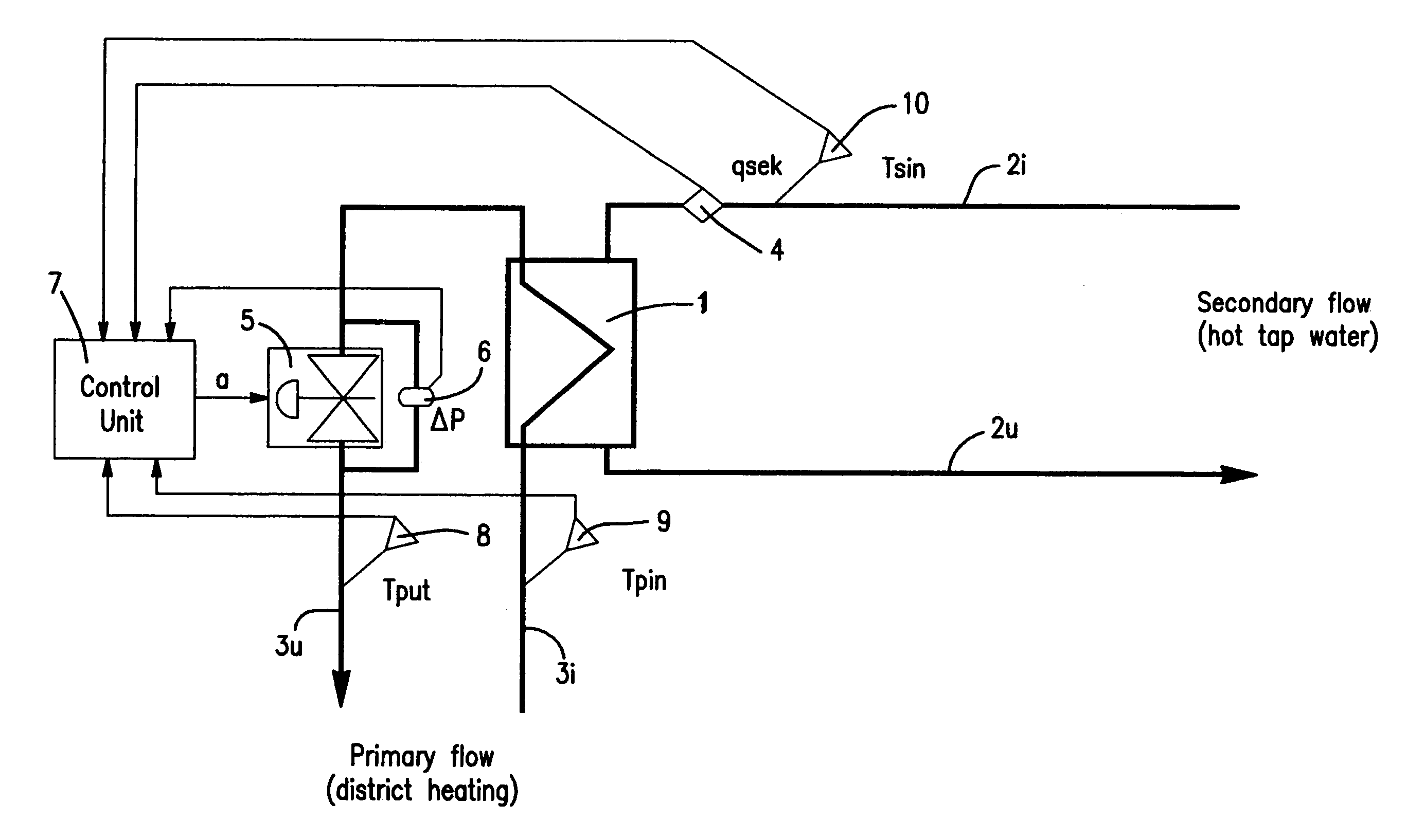
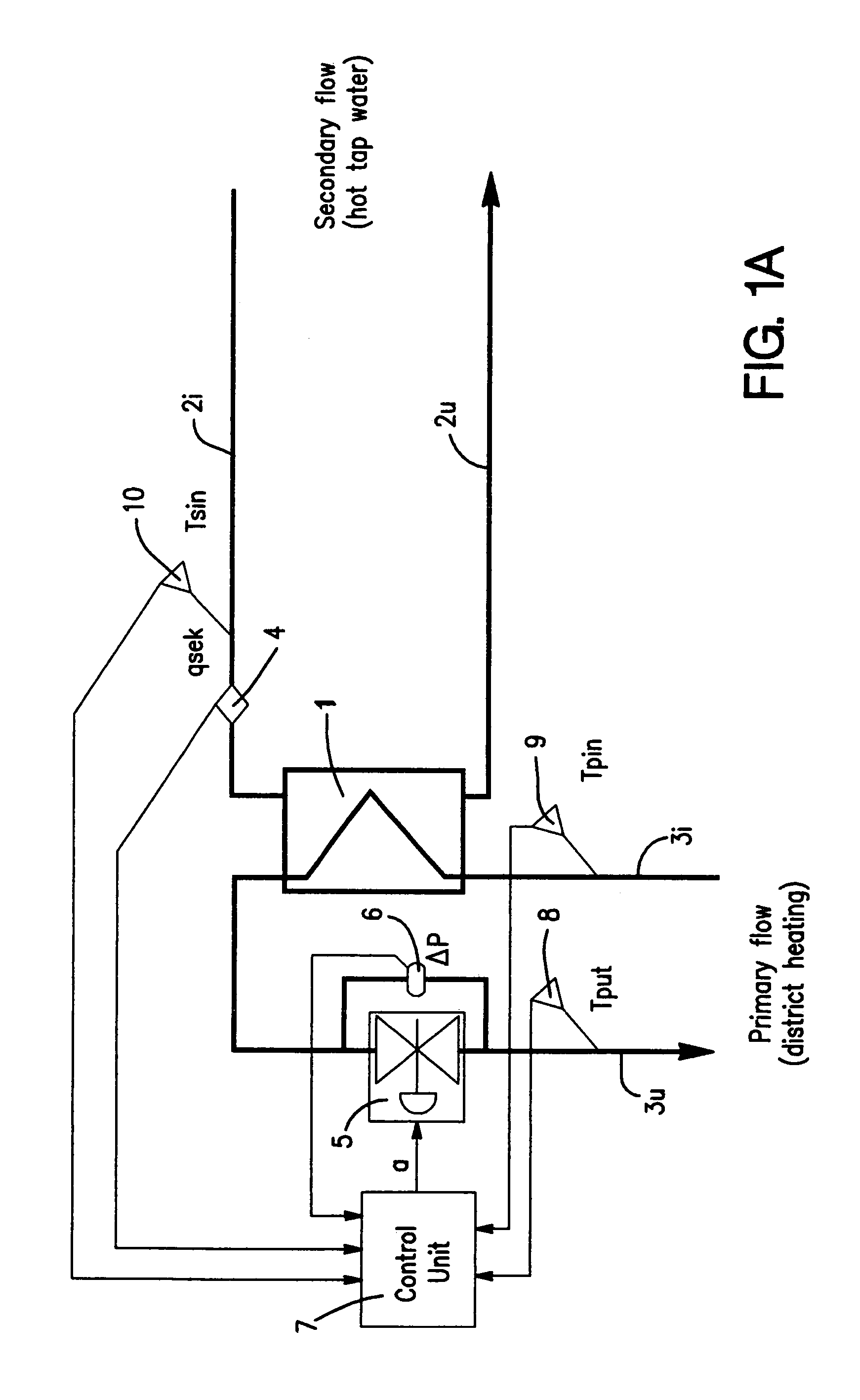
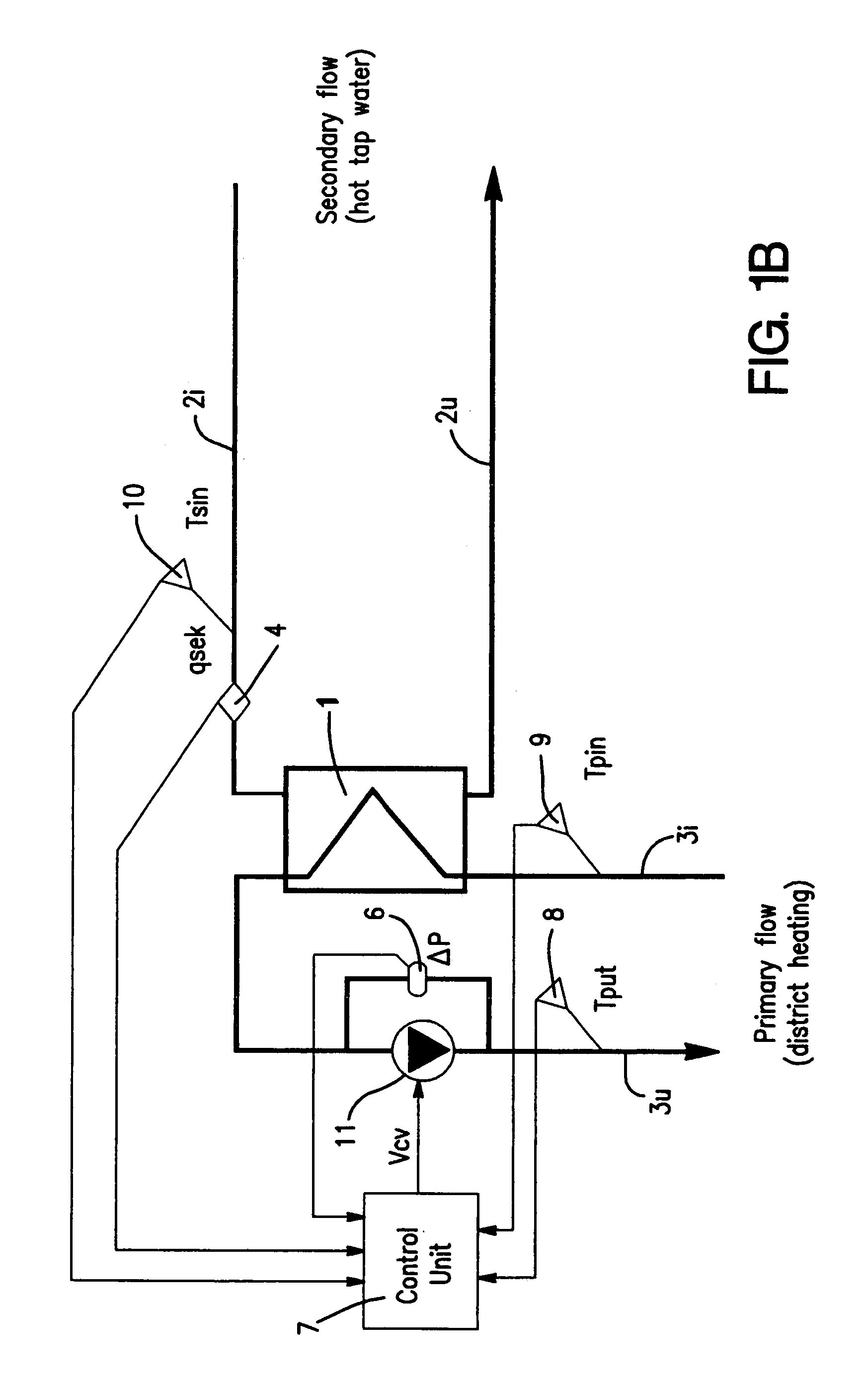
[0031]FIG. 1a shows an implementation of the invention in a district heating station of a consumer. The station comprises a heat exchanger 1, comprising a primary circuit 3, and a secondary circuit 2. The inbound primary flow 3i to the primary circuit 3 is constituted by hot water from the central heating system, while the outbound primary flow 3u is constituted by recycled water. The secondary flow 2i of the secondary circuit 2 is constituted by incoming fresh water, heated in the heat exchanger 1, while the tapped secondary flow 2i is constituted by heated hot tap water, conducted to the taps of the end consumer or the customer. When the temperature of the inbound secondary flow 2i can not be assumed to be otherwise known (for instance, through being constant and known beforehand), a temperature gauge is arranged in the inbound flow 2i (shown with dashed lines in the figures).

[0032]A flow meter 4 is arranged in the secondary circuit 2i–2u, preferably on the opening side, and the s...


PUM


Abstract

Process and device for controlling the temperature of an outbound secondary flow in a secondary circuit from a heat exchanger by a primary flow in a primary circuit, via a member that regulates the primary flow, influenced by a control unit. The enthalpy difference between inbound and outbound primary flow to and from the heat exchanger and the secondary flow are determined. The flow in the primary circuit is determined, and the parameters are supplied to the control unit for controlling the member, whereby the primary flow is controlled in dependence of the secondary flow, so that power supplied to the heat exchanger substantially equals the sum of the power needed to raise the temperature of the secondary flow from the initial temperature to the desired outbound temperature; the assumed power requirement for compensating for energy stored in the heat exchanger; and the assumed leak power from the heat exchanger.

Description

[0001]This application is a continuation of PCT / SE01 / 00952 filed May 3, 2001.[0002]The present invention relates to a method and a device for controlling the temperature of at least one outbound secondary flow in a secondary circuit from a heat exchanger through a primary flow in a primary circuit, via a control member which can be affected by a control unit, which member regulates the primary flow. The invention also relates to a method for measuring yielded power and heat quantity.BACKGROUND OF THE INVENTION AND THE PROBLEM[0003]During delivery of hot tap water in district heating station, a primary flow of centrally heated water, which is conducted into a heat exchanger, where a secondary flow of hot tap water is heated to a constant consuming temperature in the heat exchanger. Control of the constant consuming temperature on the secondary side have been obtained in the district heating station, either through automatic mechanical, or through electronic control devices, which con...

Claims


Application Information

Patent Timeline
Patent Type & Authority Patents(United States)
IPC IPC(8): F24D19/10F24D10/00F28F27/02
CPCF24D19/1051F28F27/02F24D10/003F24D19/10Y02E20/14F24D10/00Y02B30/17
Inventor LINDGREN
Owner LINDGREN
Why Eureka
Try Eureka