Carburetor air-fuel mixture adjustment assembly

a technology for air-fuel mixture and adjustment assembly, which is applied in the direction of idling devices, machines/engines, and combustion gas purification/modification, etc., can solve the problems of adversely affecting engine performance and undesirable increase of exhaust emissions, so as to reduce and increase the flow area of the orifice, inhibit the radial or lateral movement and inhibit the unintended rotation of the needle valve body

Inactive Publication Date: 2006-07-04
WALBRO LLC
View PDF25 Cites 18 Cited by
  • Summary
  • Abstract
  • Description
  • Claims
  • Application Information

AI Technical Summary

Benefits of technology

[0008]An apparatus for adjusting the air-fuel ratio of a carburetor with a needle valve body received in a receptacle of the carburetor body and having a seal between them preferably adjacent the tip and a retainer between them preferably adjacent the head of the needle valve body. The receptacle intersects a fuel passage in the carburetor main body. The needle valve body has a shank with a threaded portion between the tip and the head and is engaged with a complementary threaded portion in the receptacle so that rotation of the needle valve body axially advances and retracts the tip relative to a seat or orifice to respectively decrease and increase the flow area of the orifice through which fuel may pass. To prevent tampering with a factory setting of the needle valve body, preferably its head, may be received in a recess in the main body of the carburetor. Additionally, its head may have an unconventional, non-circular shape, thus requiring a specialized tool to rotatably adjust the needle valve body.
[0009]Preferably, a generally annular seal is concentrically disposed on the shank of the needle valve body adjacent the tip and is compressed between the receptacle and the shank. A generally annular retainer is preferably disposed concentrically on the shank adjacent the head of the needle valve body and is compressed between the receptacle and the shank. The retainer laterally biases the threaded portion of the needle valve body into engagement with an interiorly threaded portion of the receptacle and ensures alignment of the intermediate portion of the needle valve body with the receptacle, thus inhibiting radial or lateral movement of the needle valve body within the receptacle. The retainer also inhibits unintended rotation of the needle valve body. The retainer assures that a constant fuel calibration setting is maintained through the orifice by resisting axial and radial needle displacement and rotation due to such factors as external forces applied to the head of the needle valve body or engine vibration.
[0010]Another aspect of the invention provides an apparatus for adjusting the air-fuel ratio of a fuel mixture to be supplied to an engine having a main body with a retainer seat and a pair of fuel passages in communication with a pair of needle orifices. The main body has a pair of receptacles each having an interiorly threaded portion, with the receptacles communicating with a separate one of the fuel passages. A pair of needle valve bodies are received within a separate one of the receptacles, with each needle valve body including a tip, a head, an exteriorly threaded portion having a major diameter sized for complementary threaded engagement with the interiorly threaded portions of the receptacles, and an intermediate portion between the threaded portion and the head. A retainer has a pair of openings having diameters sized for a friction fit with a separate one of the intermediate portions to maintain a desired position of the needle valve bodies by inhibiting displacement of the tips relative to the needle orifices.
[0011]Objects, features and advantages of the invention include providing an assembly that maintains a fuel calibration setting in use by resisting inadvertent or unintended needle displacement between the needle valve body and the receptacle, permits use of a shorter length, reduced mass, and less expensive needle valve body, reduces the effects of vibration of the needle valve body, prevents inadvertent adjustment of the needle valve body, provides additional sealing between the needle valve body and receptacle to maintain the proper air-fuel ratio of the fuel mixture, reduces the complexity of the machining required to manufacture the needle valve body and the cost to manufacture the needle valve body, reduces offset or eccentricity between the needle valve body and the receptacle, and improves the ease and efficiency of manufacturing and assembly of a carburetor air-fuel mixture adjustment assembly.

Problems solved by technology

Fuel flow rate changes caused by needle “slop” can result in excessively rich or lean fuel mixtures that undesirably increase exhaust emissions and / or adversely affect engine performance.

Method used


Image

  • Carburetor air-fuel mixture adjustment assembly
  • Carburetor air-fuel mixture adjustment assembly
  • Carburetor air-fuel mixture adjustment assembly

Examples


Embodiment Construction

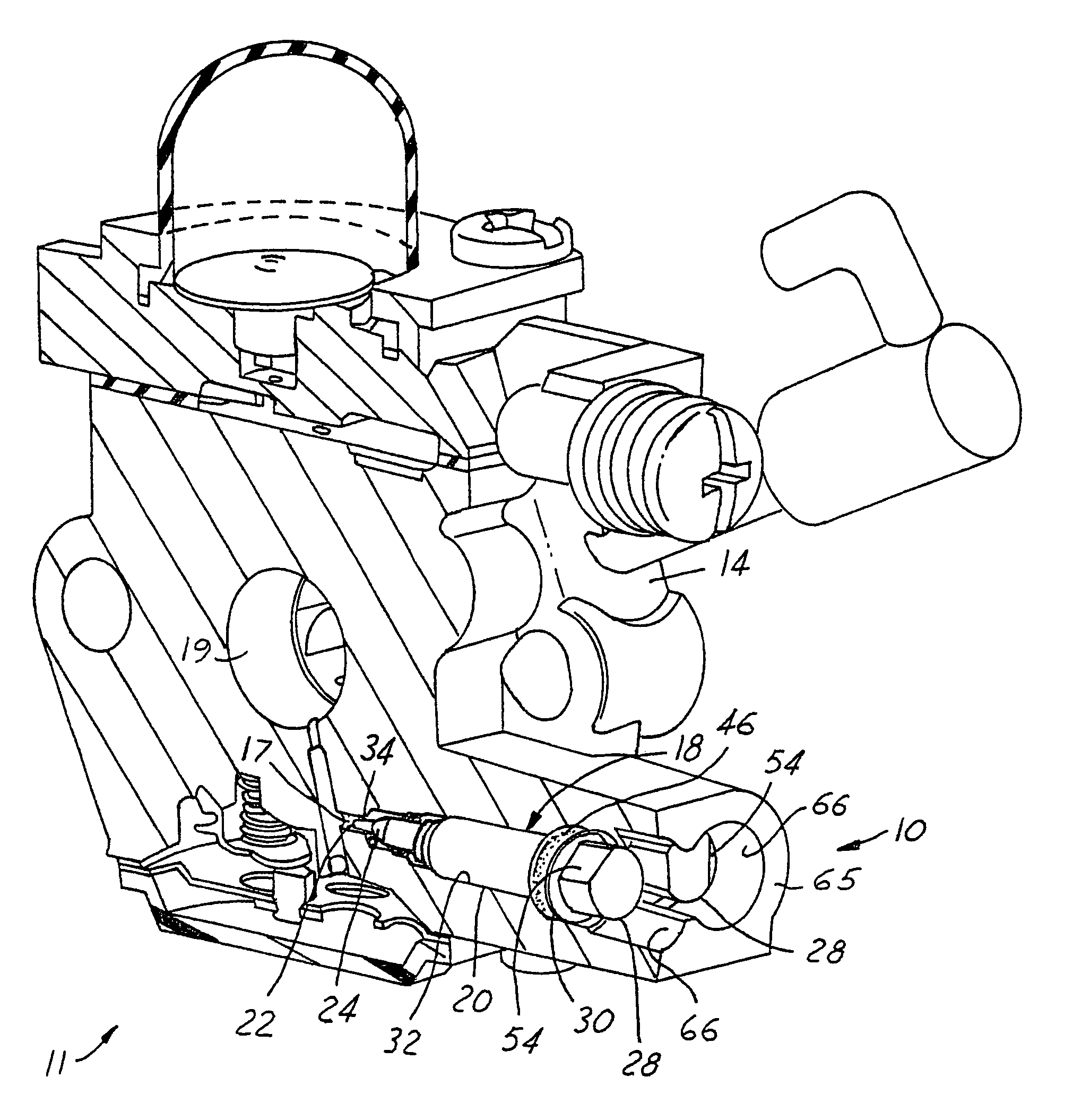
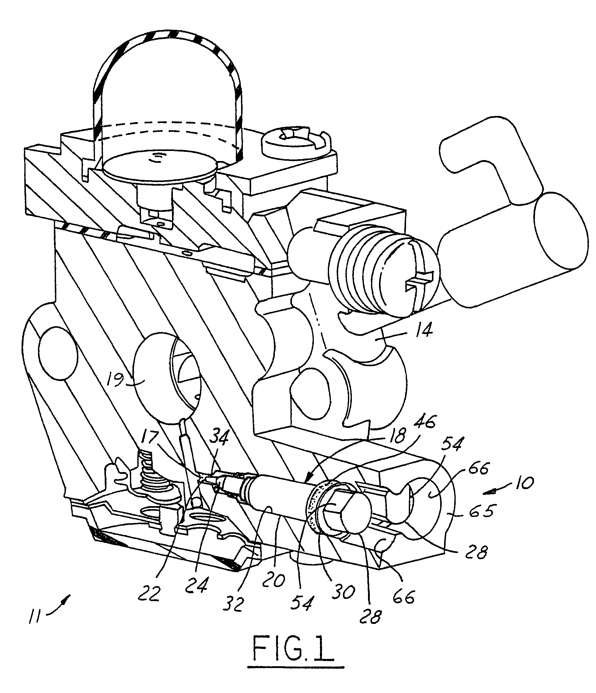
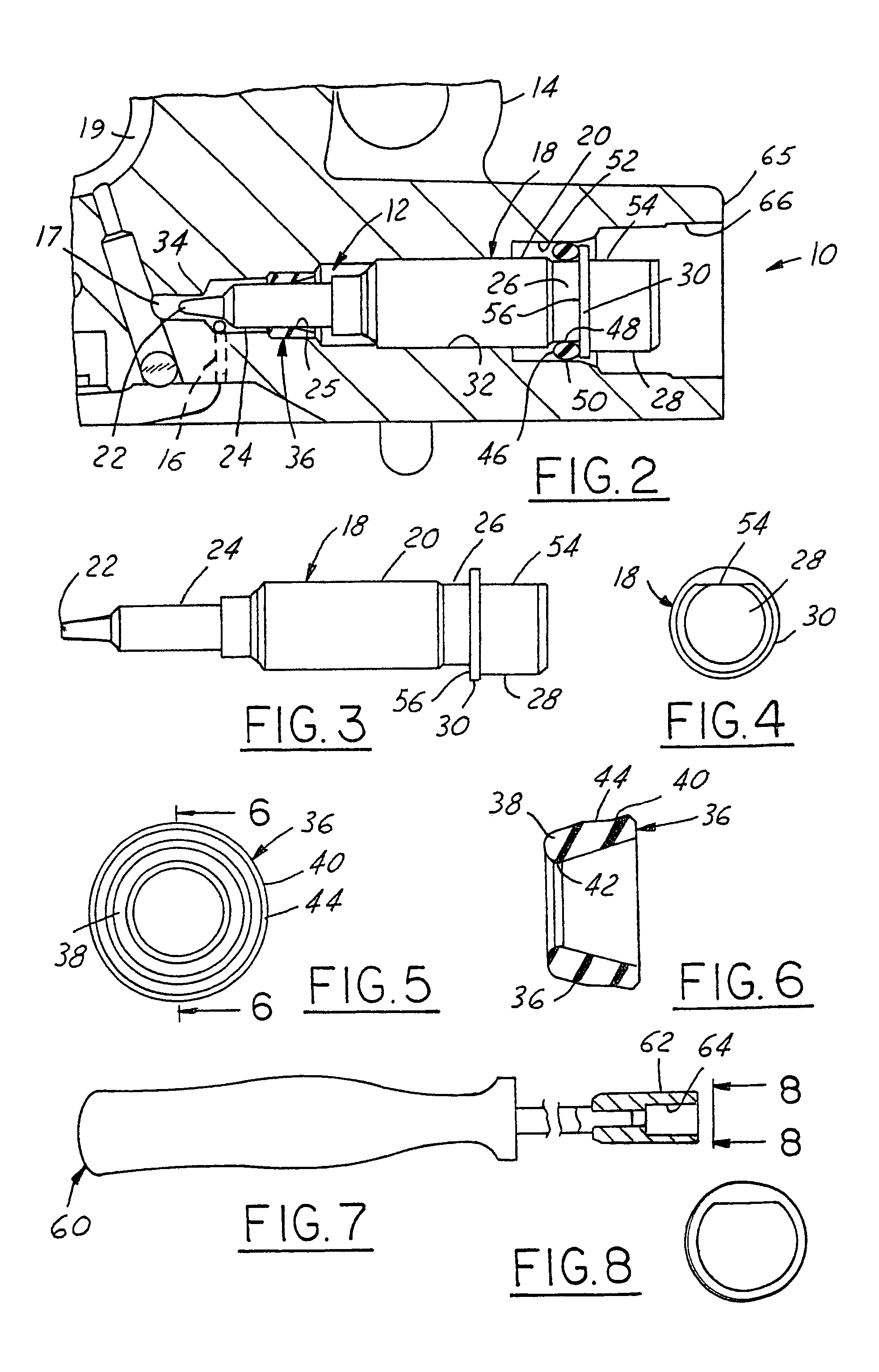
[0032]FIGS. 1 and 2 illustrate an apparatus 10 embodying this invention for adjusting the air-fuel ratio of a fuel mixture supplied by a carburetor 11. The apparatus 10 includes a receptacle 12 formed in a main body 14 of a carburetor and a needle valve body 18 having a tip 22 concentrically supported within the receptacle 12 so that in operation, the tip 22 is disposed in an axially aligned orientation relative to a seat or orifice 34. The tip 22 can be axially advanced and retracted by rotating the needle valve body 18 within the receptacle 12. This axial movement of the tip 22 relative to the orifice 34 changes the effective flow area of the orifice 34 to adjust the air-fuel ratio of the fuel mixture.

[0033]Carburetor 11 may be a diaphragm carburetor, float bowl carburetor or other type of carburetor which utilizes a needle valve to adjust the air-fuel ratio of a fuel mixture supplied by the carburetor. The carburetor body 14 has a first fuel passage 16 and a second fuel passage 1...


PUM

PropertyMeasurementUnit
angleaaaaaaaaaa
angleaaaaaaaaaa
angleaaaaaaaaaa

Abstract

An apparatus for adjusting the air-fuel ratio of a fuel mixture to be supplied to an engine. The apparatus has a pair of needle valve bodies and a pair of receptacles formed in a main body of a carburetor for receiving the needle valve bodies. Each needle valve body has a needle and a head. The needles are axially movable relative to a respective needle orifice. The needles may be axially advanced and retracted by rotating the needle valve bodies within the receptacles to respectively decrease and increase the flow of the fuel mixture around the needles and through the orifices. To prevent tampering with the needle valve body setting, the head of the needle valve body has an unconventional shape requiring a specialized tool to rotatably adjust the needle valve body. To further prevent tampering, the head is recessed with the main body of the carburetor. A retainer is disposed in the main body of the carburetor and receives the needle valve bodies to facilitate maintaining alignment of the needle valve bodies relative to the receptacles. The retainer assures that a constant fuel calibration setting is maintained through the orifices by resisting displacement of the needles due to such factors as external forces applied to the head of the needle valve body or engine vibration.

Description

REFERENCE TO RELATED APPLICATION[0001]This application is a Continuation-In-Part of U.S. patent application Ser. No. 10 / 955,869 filed Sep. 30, 2004, now abandoned which is a Continuation-In-Part of U.S. patent application Ser. No. 10 / 341,648, filed Jan. 14, 2003 and now abandoned, and each of which claims the benefit of U.S. Provisional Application No. 60 / 395,030, filed Jul. 11, 2002.FIELD OF THE INVENTION[0002]This invention relates generally to a carburetor fuel mixture adjustment assembly for adjusting the air-fuel ratio of a fuel mixture to be supplied to an engine.BACKGROUND OF THE INVENTION[0003]It is known for a carburetor air-fuel mixture adjustment assembly to include a needle valve body that is threaded into a bore in a carburetor main body. The bore in such an assembly intersects a fuel passage in the carburetor main body. The needle valve body has a shank with a tip, a head and an exteriorly threaded portion between them received in a complementary threaded portion of th...

Claims


Application Information

Patent Timeline
Patent Type & Authority Patents(United States)
IPC IPC(8): F02M3/08F02M9/08F02M3/10F02M17/40F02M19/00F02M19/04
CPCF02M3/10F02M19/04Y10S261/84Y10S261/38Y10T137/7062
Inventor DOW, PAUL J.OGASAWARA, HIROKITAKAHASHI, TETSUYATAKAHASHI, TOSHIMASAVIMERCATI, GIOVANNI
Owner WALBRO LLC
Why Eureka
Try Eureka