Liquid jet head

a liquid jet and jet head technology, applied in the direction of liquid spraying apparatus, printing, inking apparatus, etc., can solve the problems of inability to correct the obstruction of the flow path, the open air in the damper chamber b>12/b>, and the inability to disperse moisture from the liquid, so as to suppress the unsatisfactory dispersion of moisture from the liquid and prevent the increase of the viscosity of the liquid in the liquid reservoir

Inactive Publication Date: 2006-07-04
SEIKO EPSON CORP
View PDF18 Cites 22 Cited by
  • Summary
  • Abstract
  • Description
  • Claims
  • Application Information

AI Technical Summary

Benefits of technology

[0015]The flow of water vapor from the liquid that passes through the seal plate is therefore restricted by the flow resistance of the control path, and undesirable dispersion of moisture from the liquid is thus suppressed.
[0062]When the seal plate is bonded to the pressure generation chamber and liquid reservoir opening, this configuration can firmly hold the seal plate at the bonding pad, thereby reducing the likelihood of bonding defects.

Problems solved by technology

A problem with the conventional recording head described above is that the damper chamber 12 is open to the air.
The ink can even dry to the point that clogging of the flow path cannot be corrected and ink cannot be normally discharged even after a cleaning operation, for example, that forcibly vacuums ink from within the ink path when the recording head is used the next time.

Method used


Image

  • Liquid jet head
  • Liquid jet head
  • Liquid jet head

Examples


embodiment 1

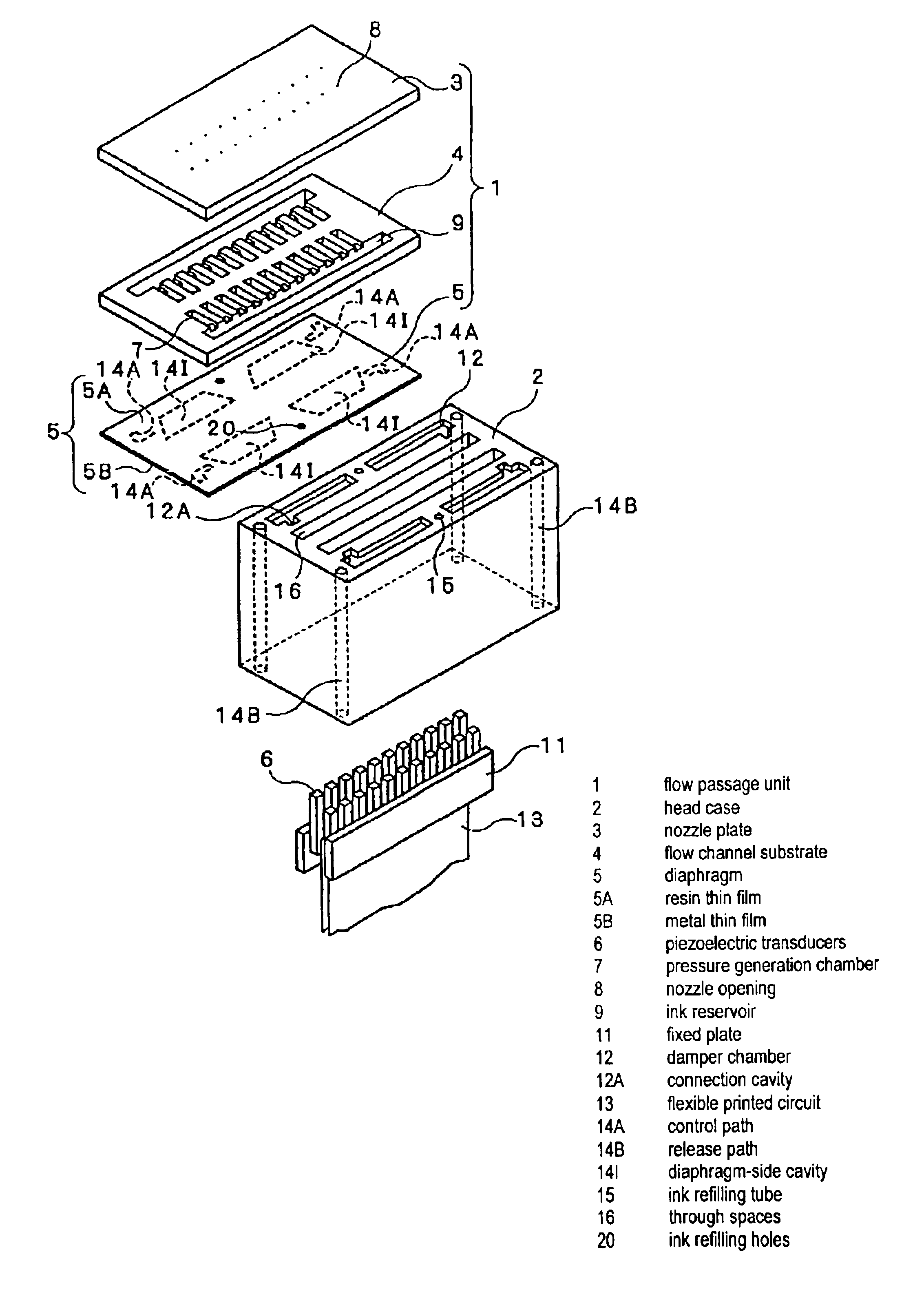
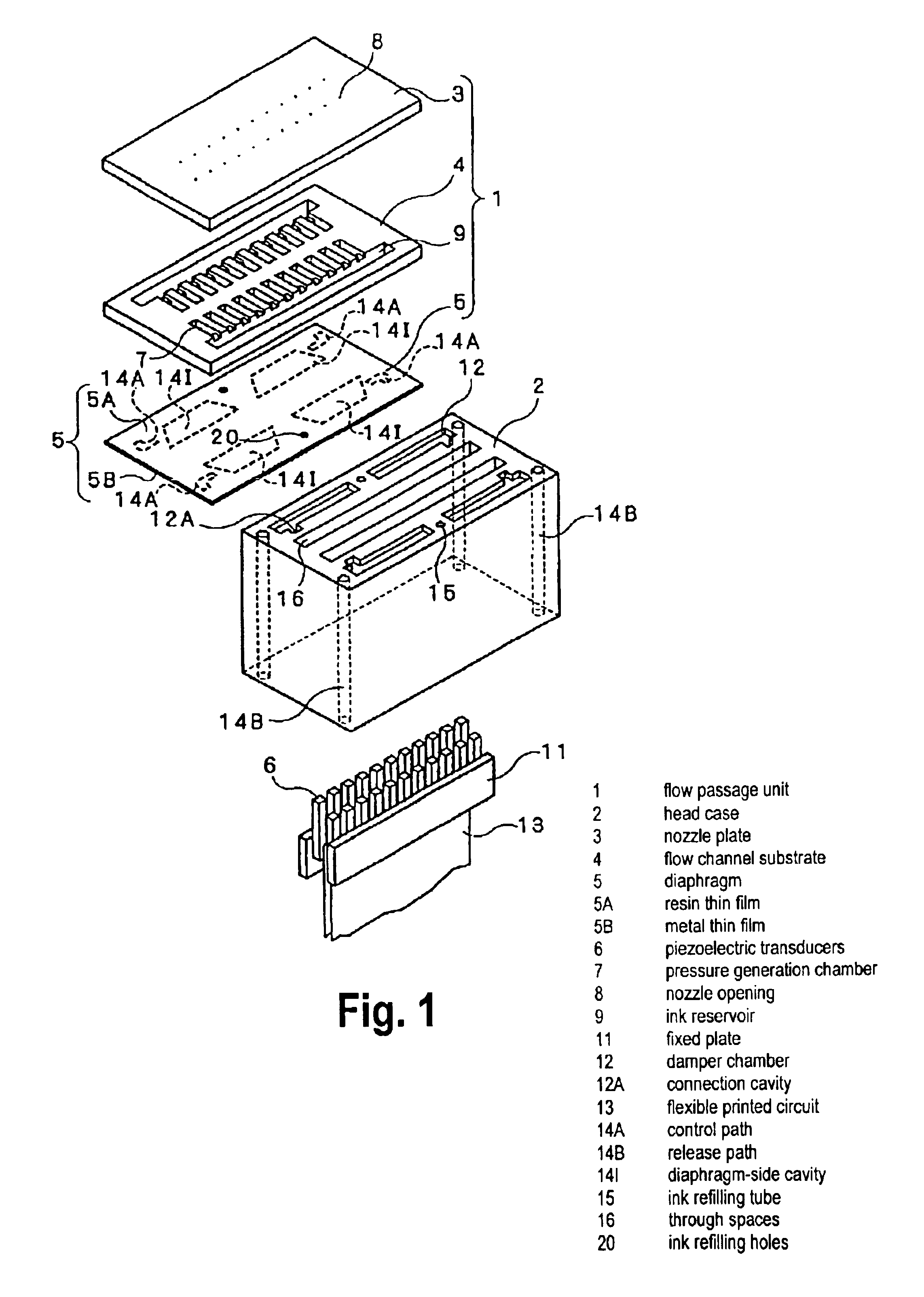
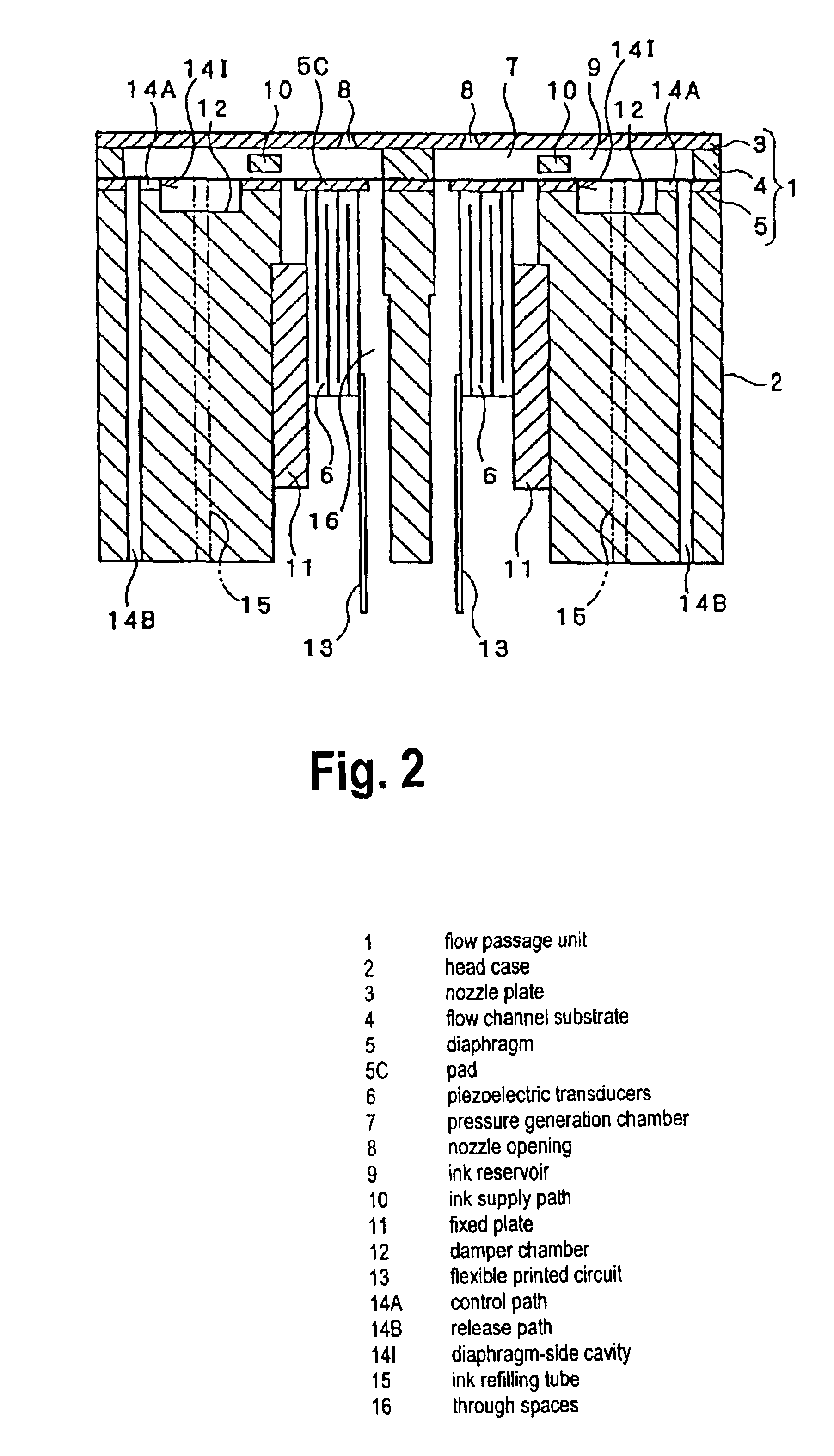
[0083]FIG. 1 to FIG. 7 show an inkjet recording head (referred to below simply as a recording head) as a first embodiment of an inkjet recording head disposed to an inkjet recording apparatus according to the present invention. This recording head is basically the same as the recording head shown in FIG. 16, and like parts are therefore identified by like reference numerals below. Furthermore, while there are two rows of nozzle openings 8 and pressure generation chambers 7 in the recording head shown in FIG. 16, there are four such rows in the head case 2 shown in FIG. 3. More specifically, the section through either side of the dot-dash line L in FIG. 3 corresponds to the views shown in FIG. 1, FIG. 2, and FIG. 16. FIG. 3 is a top plan view of the head case 2.

[0084]The ink path unit 1 is a laminar construction including a nozzle plate 3 to which nozzle openings 8 are disposed in rows, a flow channel substrate 4 in which rows of pressure generation chambers 7 each communicating with...

embodiment 2

[0104]A second embodiment of the present invention is described with reference to FIG. 3 and FIG. 8. In this embodiment the connection cavities 12A of plural damper chambers 12 communicate with each other. As a result two control paths 14A communicate with the mutually communicating connection cavities 12A as will be clear from the double-dot dash line in FIG. 3. The other ends of the two control paths 14A are connected to one release path 14B. It is also possible to use only one or to use three or more control paths 14A.

[0105]Because connection cavities 12A communicate with each other in this embodiment, ink vapor from two damper chambers 12 can be conducted with a simple construction. In addition, when a problem occurs with flow through one control path 14A, deficient yet minimal flow control is sustained by the other control path 14A. Ink viscosity can therefore be prevented from reaching a worst-case condition, and a pressure drop in the damper chambers can be suppressed.

embodiment 3

[0106]A third embodiment of the invention is shown in FIG. 9 and FIG. 10. In this embodiment the control paths 14A are formed in the head case 2. FIG. 9 shows the control path 14A inset into the surface of the head case 2 facing the diaphragm (seal) 5. FIG. 10 shows the control path 14A disposed as a narrow ventilation hole in the head case 2. Note that a connection cavity 12A is not present in the configuration shown in FIG. 10.

[0107]This embodiment is advantageous in terms of manufacturability because the control path 14A can be formed at the same time the head case 2 is manufactured.


PUM


Abstract

A liquid jet head and apparatus prevent an increase in the viscosity of liquid in the liquid path during long term storage. The recording head has a liquid path unit 1 with nozzle openings 8, pressure generation chambers 7, liquid reservoirs 9, and a diaphragm 5, and a head case 2 bonded to the liquid path unit 1. A damper chamber 12 for releasing pressure change inside the liquid reservoir is formed at a part of the head case or seal plate 5 corresponding to the liquid reservoir 9. A release path 14B for releasing pressure in the damper chamber to the air is formed in the head case. A control path 14A communicating with the damper chamber and release path and having a specific flow resistance restricting dispersion of moisture vapor from the liquid is formed in the head case and / or seal plate.

Description

BACKGROUND OF THE INVENTION[0001]1. Field of the Invention[0002]The present invention relates to a liquid jet head, and a liquid jet apparatus, such as a recording head for an ink jet recording apparatus, an electrode member ejection head for an electrode forming apparatus, an organic substance jet head for a bio chip manufacture apparatus, etc., in which liquid is ejected by deformation of piezoelectric elements formed on a surface of a diaphragm formed as a part of pressure generating chambers communicating with nozzle orifices from which liquid is ejected.[0003]2. Description of Related Art[0004]A typical inkjet recording head (a kind of liquid jet head) using a longitudinally oscillating piezoelectric transducer (referred to below as simply a “recording head”) has, as shown in FIG. 16, an ink path unit 1 in which a plurality of nozzle openings 8 and a pressure generation chamber 7 are formed, and a head case 2 to which this ink path unit 1 is bonded and in which piezoelectric tr...

Claims


Application Information

Patent Timeline
Patent Type & Authority Patents(United States)
IPC IPC(8): B41J2/045B41J2/17B05B17/06B41J2/05B41J2/055B41J2/14B41J2/16
CPCB41J2/055B41J2/14016B41J2/14274B41J2/175B41J2/16526B41J2/17596B41J2002/1437B41J2202/11B41J2/16532B41J2002/14419
Inventor OKAZAWA, NORIAKI
Owner SEIKO EPSON CORP
Why Eureka
Try Eureka