Differential amplifier with a common mode voltage loop

a technology of voltage loop and differential amplifier, which is applied in the direction of amplifier modification, amplifier to reduce detrimental interference, electric apparatus, etc., can solve the problems of reducing accuracy and enhancing the sensitivity of the common mode correction chain, and achieve the effect of stabilizing the amplification chain

Inactive Publication Date: 2006-07-04
ST ERICSSON SA
View PDF4 Cites 26 Cited by
  • Summary
  • Abstract
  • Description
  • Claims
  • Application Information

AI Technical Summary

Benefits of technology

[0015]According to an embodiment of the present invention, the stability of the amplification chain is ensured by two identical second capacitors, each arranged between one input and one output of the output stage; and the fi

Problems solved by technology

Such a reduction especially results in reducing the accuracy and enhancing the sensitivity of the com

Method used


Image

  • Differential amplifier with a common mode voltage loop
  • Differential amplifier with a common mode voltage loop
  • Differential amplifier with a common mode voltage loop

Examples


Embodiment Construction

[0034]The following discussion is presented to enable a person skilled in the art to make and use the invention. Various modifications to the embodiments will be readily apparent to those skilled in the art, and the generic principles herein may be applied to other embodiments and applications without departing from the spirit and scope of the present invention. Thus, the present invention is not intended to be limited to the embodiments shown, but is to be accorded the widest scope consistent with the principles and features disclosed herein.

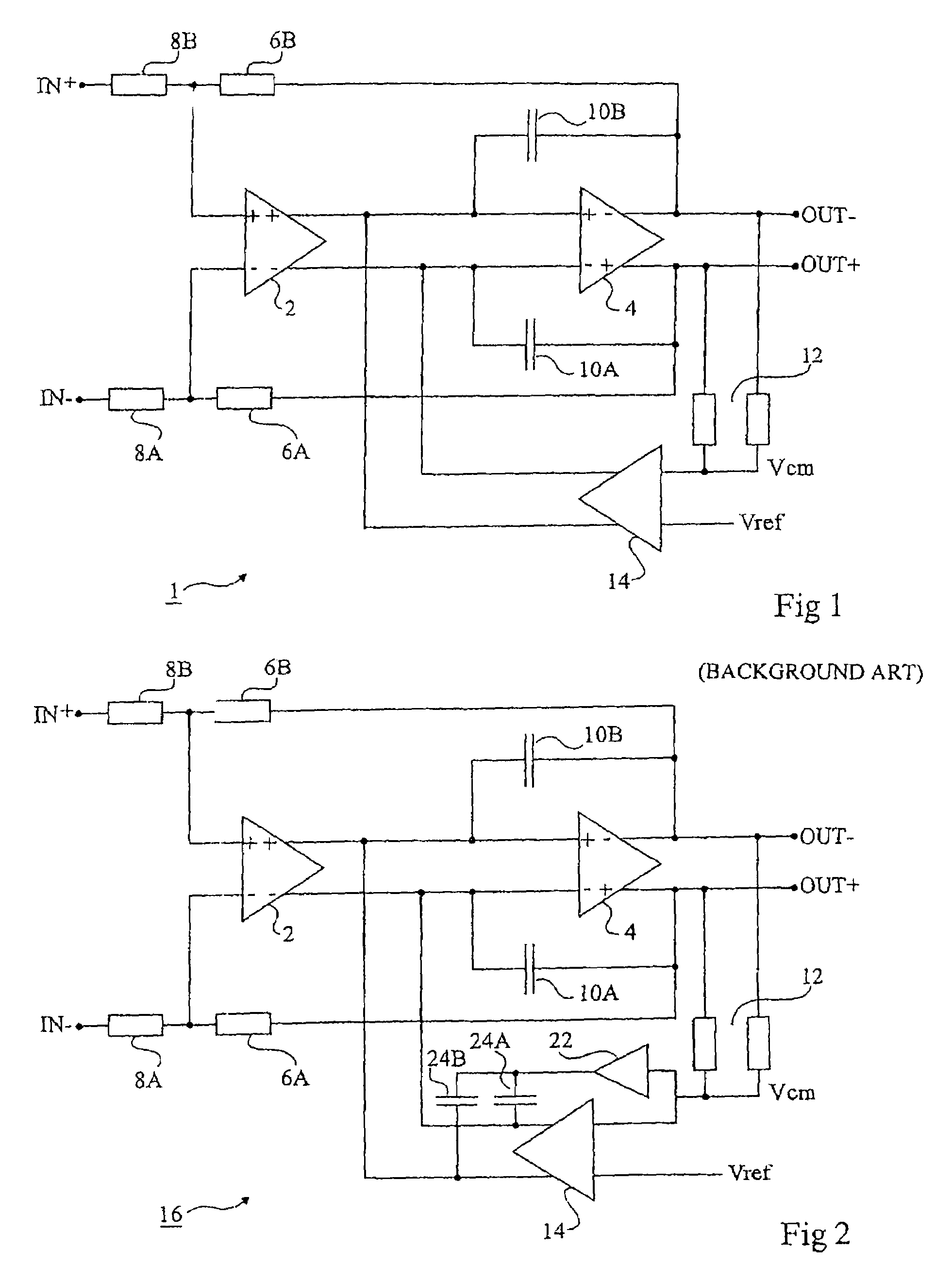
[0035]Same elements have been designated with same reference numerals in the different drawings. Only those elements that are necessary to the understanding of the present invention have been shown.

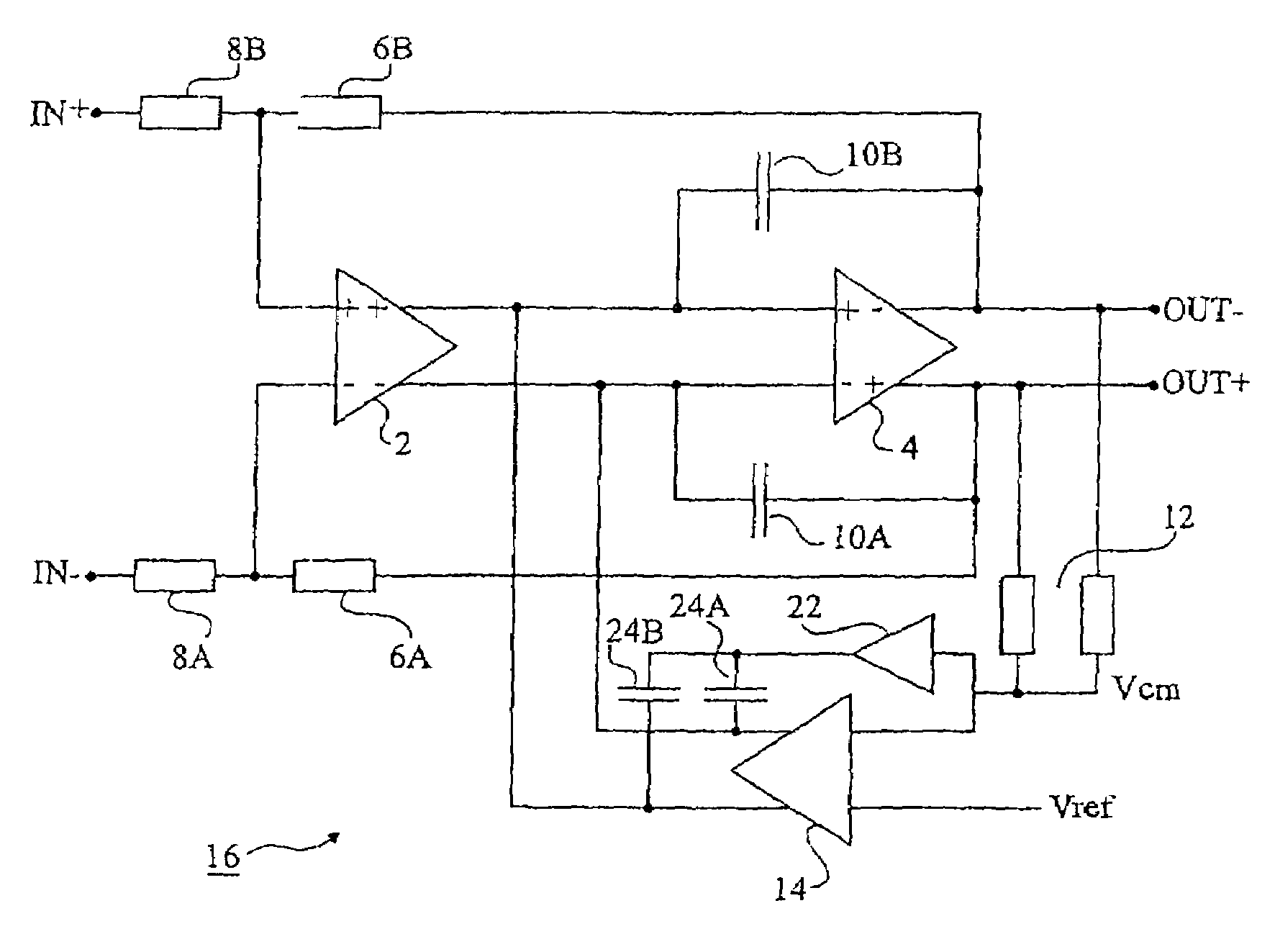
[0036]A contribution of the present inventor has been to note that, although the common mode correction block introduces a phase shift likely to cause a circuit instability, this phase shift is only significant, for stability, for frequencies close t...


PUM


Abstract

An amplifier circuit comprising an amplification chain having a differential output stage; a common mode correction block acting on the input of the output stage as a function of a common mode voltage at the output of said stage and introducing a phase shift between its input and its output for frequencies close to the cut-off frequency of the circuit; and, in parallel with the correction block, a means introducing no phase shift between its input and its output and having at frequencies greater than or equal to the circuit cut-off frequency an output impedance much smaller than the output impedance of the correction block.

Description

PRIORITY CLAIM[0001]This application claims priority from French patent application No. 03 / 04829, filed Apr. 17, 2003, which is incorporated herein by reference.BACKGROUND[0002]1. Technical Field[0003]The present invention relates to the field of integrated circuits, and more specifically relates to amplifiers with a differential output.[0004]2. Discussion of the Related Art[0005]FIG. 1 schematically shows a feedback amplifier circuit 1 having a differential input and a differential output comprising a transconductance amplifier stage 2 having two output terminals “+” and “−” respectively connected to two inputs “+” and “−” of a transconductance inverter amplifier 4. The feedback loop of the amplifier comprises two impedances 6A, 6B respectively connecting output terminals “+” and “−” of stage 4 to input terminals “−” and “+” of stage 2. Two impedances 8B, 8A connect input terminals “+” and “−” of stage 2 to two input terminals (IN+, IN−) of circuit 1. Impedances 8 (8A, 8B) form a v...

Claims


Application Information

Patent Timeline
IPC IPC(8): H03F3/45H03F1/08
CPCH03F1/086H03F3/45941H03F3/45645
Inventor VAN ZANTEN, FRANCOIS
Owner ST ERICSSON SA
Why Eureka
Try Eureka