Micro surface mount coil unit

a coil unit and surface mount technology, applied in the direction of transformer/react mounting/support/suspension, inductance with magnetic core, inductance, etc., can solve the problem of difficult to mount the coil unit with high density, the coil unit is attached to a position different from the designed position, and the coil unit is difficult to be mounted with high density. problems, to avoid the occurrence of positional shift, poor soldering, and the effect of decreasing the width of the coil winding

Inactive Publication Date: 2006-07-04
SUMIDA CORP
View PDF6 Cites 18 Cited by
  • Summary
  • Abstract
  • Description
  • Claims
  • Application Information

AI Technical Summary

Benefits of technology

[0019]The present invention has been made in view of the above situation, and accordingly an object thereof is to provide a micro surface mount coil unit capable of avoiding the occurrence of positional shift and poor soldering at the time of soldering of the coil unit without decreasing the width of a coil winding portion of the coil form, capable of improving the packaging density of a circuit board, and capable of increasing the shock resistance of coil unit.

Problems solved by technology

As a result, when the bottom surface of the lead frame 212 is soldered onto the circuit board pattern to which cream solder is applied, the lead frame slips on the solder melted by heating (reflow solder), so that the coil unit turns or shifts laterally with respect to the circuit board pattern, resulting in a fear that the coil unit is attached to a position different from the designed position.
Also, the molten solder moves and spreads on the outside surface of the lead frame, so that the quantity of solder actually contributing to the connection with the pattern decreases, which may result in poor soldering.
Further, there arises a need for increasing the width of the circuit board pattern (land size), which poses a problem in that it is difficult for the coil unit to be mounted with high density according to the decrease in assembled component size.

Method used


Image

  • Micro surface mount coil unit
  • Micro surface mount coil unit
  • Micro surface mount coil unit

Examples


first embodiment

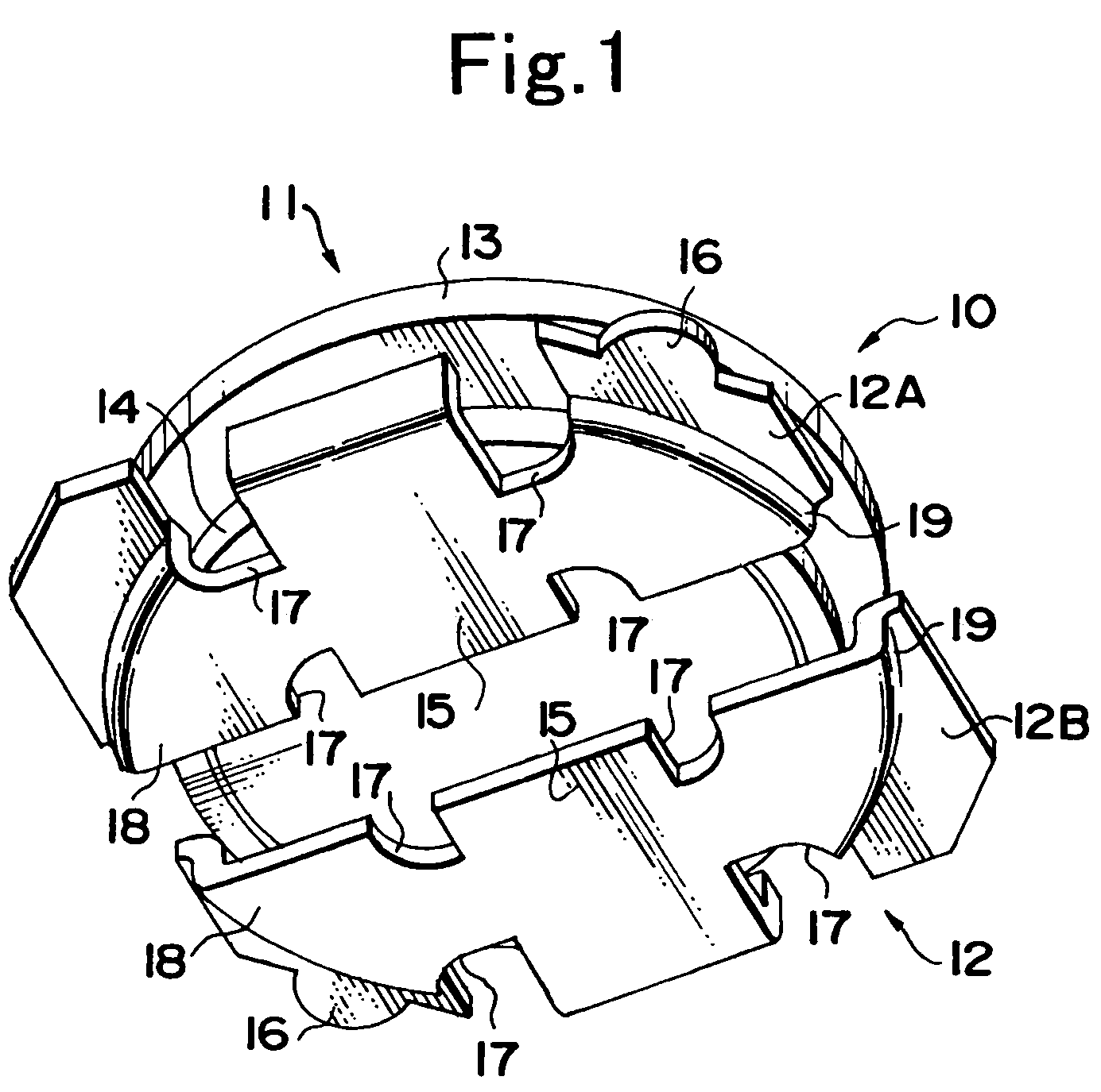
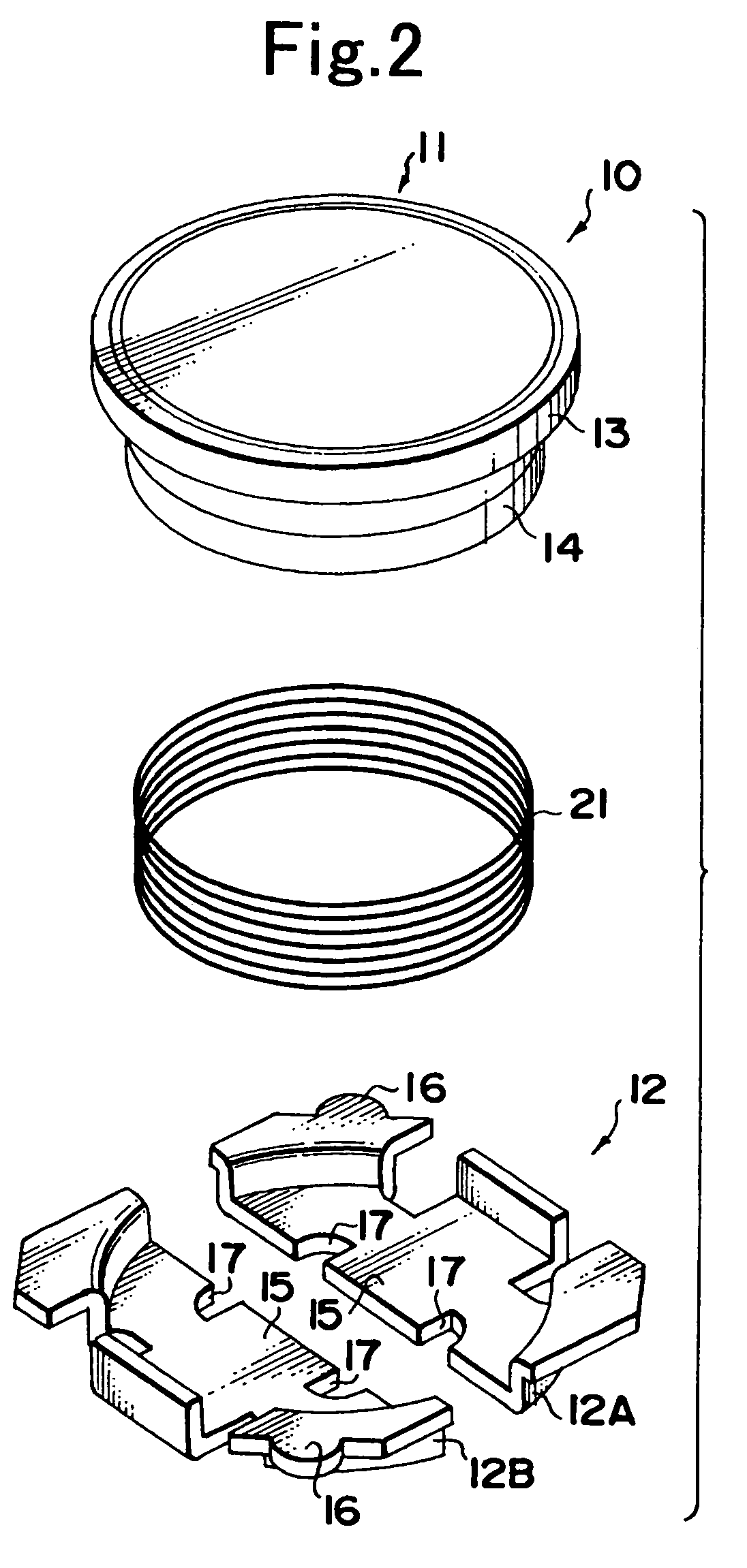
[0037]FIG. 1 is a perspective view of a micro surface mount coil unit in accordance with a first embodiment of the present invention, viewed from the bottom surface side, and FIG. 2 is an exploded perspective view of the micro surface mount coil unit.

[0038]This micro surface mount coil unit 10 is surface mounted on a circuit board of electronic equipment especially required to be small and thin, such as cellular phones, digital cameras, notebook type personal computers, and mobile computing devices including electronic notebooks. The coil unit 10 is provided with a drum-shaped core 11 in which a columnar coil form part (not shown in FIGS. 1 and 2; refer to a coil form part 131 in FIG. 5(A)) and a disk-shaped flange parts 13 and 14 extendedly provided at both ends of a coil form part are integrally formed of ferrite.

[0039]A coil 21 is wound around the coil form part of the drum-shaped core 11 so as to be held between the upper flange part 13 and the lower flange part 14 (the lower fl...

second embodiment

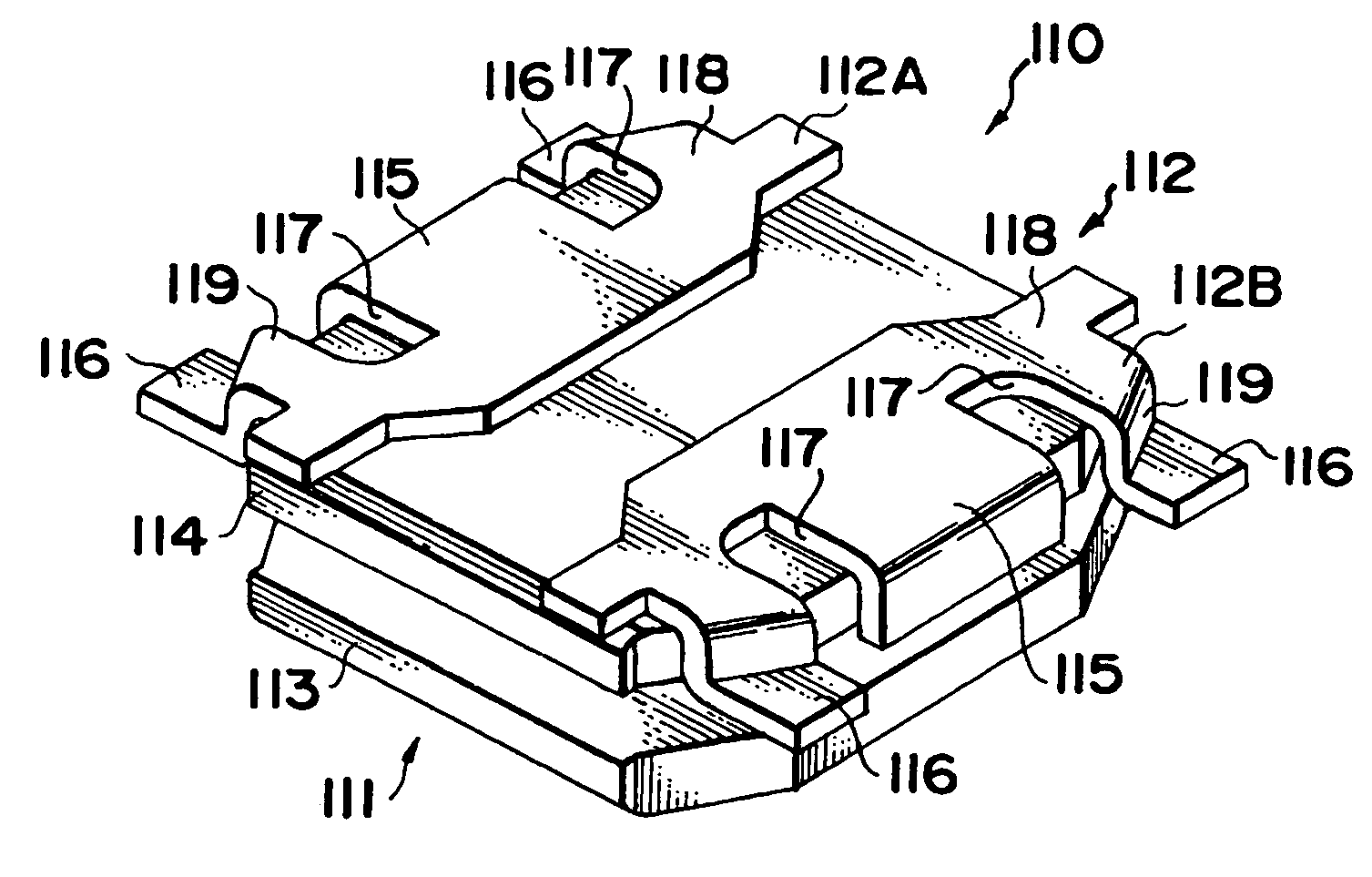
[0053]FIGS. 3A and 3B are perspective views of a micro surface mount coil unit in accordance with a second embodiment, FIG. 3A being viewed from the top surface side, and FIG. 3B being viewed from the bottom surface side; and FIG. 4 is an exploded perspective view of the micro surface mount coil unit.

[0054]This micro surface mount coil unit 110 has almost the same construction as that of the micro surface mount coil unit 10 of the first embodiment except that upper and lower flange parts 113 and 114 of a drum-shaped core 111 has a substantially rectangular shape the four corners of which are chamfered. Therefore, in FIGS. 3A, 3B and 4, reference numerals that are obtained by adding 100 to the reference numerals applied in FIGS. 1 and 2 are applied to elements corresponding to the elements of the micro surface mount coil unit 10 of the first embodiment shown in FIGS. 1 and 2, and only the schematic construction is described, the explanation of the details being omitted.

[0055]This mic...


PUM

PropertyMeasurementUnit
axial lengthaaaaaaaaaa

Abstract

There is provided a micro surface mount coil unit in which the occurrence of positional shift and poor soldering at the time of soldering of the coil unit is avoided without decreasing the width of a coil winding portion of coil form, and the shock resistance of coil unit is increased. The coil unit 10 has a drum-shaped core 11 in which a coil form part around which a coil wire is wound is arranged between flange parts 13 and 14 and a lead frame 12 bondingly fixed to the lower flange part 14. The lead frame 12 has left and right lead frame parts 12A and 12B bonded to the lower flange part 14, and the outside surface of a bottom surface 18 of each of the lead frame parts 12A and 12B is separated into a first region forming an external connecting terminal 15 and a second region not forming the external connecting terminal 15 by notches 17.

Description

RELATED APPLICATIONS[0001]This application claims the priority of Japanese Patent Application No. 2003-278246 filed on Jul. 23, 2003, which is incorporated herein by reference.BACKGROUND OF THE INVENTION[0002]1. Field of the Invention[0003]The present invention relates to a micro surface mount coil unit suitable for electronic equipment especially required to be small and thin, such as cellular phones, digital cameras, notebook type personal computers, and mobile computing devices including electronic notebooks.[0004]2. Description of the Prior Art[0005]In recent years, with the widespread use of electronic equipment etc. especially required to be micro, such as cellular phones, a coil unit used in the electronic equipment has been required to be significantly small in size.[0006]As a coil unit capable of being significantly miniaturized, a surface mount coil unit attached to a circuit board, for example, as shown in FIGS. 6A and 6B, is known.[0007]A coil unit 210 shown in FIGS. 6A ...

Claims


Application Information

Patent Timeline
Patent Type & Authority Patents(United States)
IPC IPC(8): H01F27/02H01F5/04H01F27/06H01F17/04H01F27/29
CPCH01F27/292H01F27/027H01F17/045H01F5/04
Inventor OKI, JUICHI
Owner SUMIDA CORP
Why Eureka
Try Eureka