Truck acoustic data analyzer system

a technology of acoustic data and analyzer, which is applied in the field of traffic monitoring systems, can solve the problems of disadvantages of wire loop systems, and inability to detect motor vehicles, so as to achieve the effect of maximizing the reliability of speed measurements

Inactive Publication Date: 2006-07-04
UT BATTELLE LLC
View PDF20 Cites 25 Cited by
  • Summary
  • Abstract
  • Description
  • Claims
  • Application Information

AI Technical Summary

Benefits of technology

[0013]This invention acquires and analyzes the acoustic signature given off by a large truck or other vehicle as it travels down the highway. Tests have demonstrated that the acoustic signature of a truck driving by an acoustic sensor (microphone) can provide enough information to estimate the truck speed in miles-per-hour (mph), engine speed in rotations-per-minute (RPM), and turbocharger speed in RPM. The Truck Acoustic Data Analyzer (TADA) system provides a new means of remotely detecting these parameters for a variety of potential purposes, such as monitoring the speed of trucks and other vehicles in a manner that would be undetectable by the drivers of those vehicles. In addition, the three speed parameters measured by the TADA are altogether indicative of how heavily loaded the vehicle is and provide a means for measuring vehicle weight. These can also be useful in measuring / monitoring vehicles remotely in an undetectable way. Hardware needed by the portable system is minimal, and consists of that which is needed to record a standard sound file, for example a Windows® sound file, as the truck drives by the measurement location. Specially-developed software then analyzes the sound file and provides the speed measurements, as well as determining data quality in order to maximize the reliability of the speed measurements.

Problems solved by technology

The use of wire loops was, however, disadvantageous for several reasons.
First, a wire loop system did not detect a motor vehicle unless the motor vehicle included sufficient ferromagnetic material to create a noticeable perturbation in the inductance in the wire loop.
Because the trend now is to fabricate motor vehicles with non-ferromagnetic alloys, plastics and composite materials, wire loop systems will increasingly fail to detect the presence of motor vehicles.
Another disadvantage of wire loop systems was that they were expensive to install and maintain.
Often too, harsh weather precluded this operation for several months.

Method used


Image

  • Truck acoustic data analyzer system
  • Truck acoustic data analyzer system
  • Truck acoustic data analyzer system

Examples


Embodiment Construction

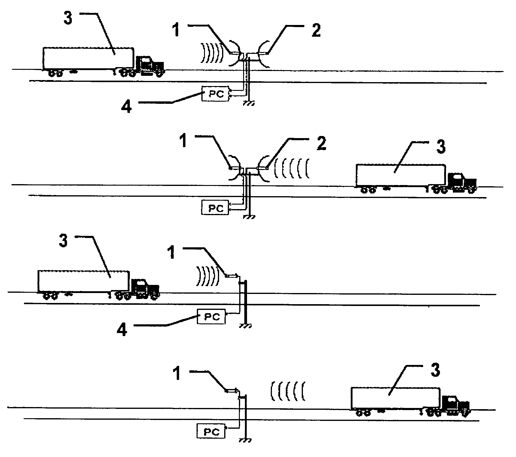
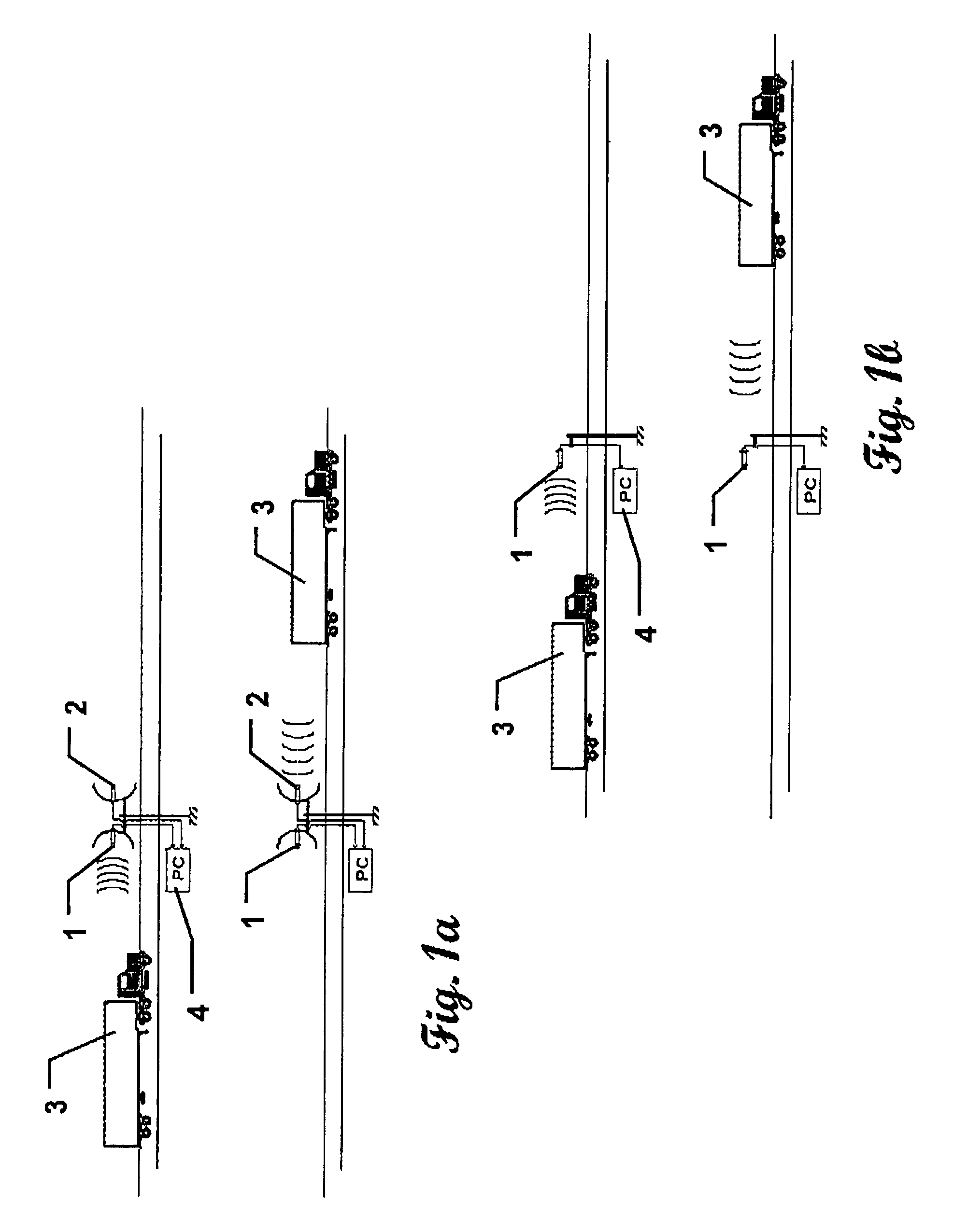
[0021]The TADA system is comprised of hardware and software, which together provide the full functioning capabilities of the system. FIGS. 1a and 1b illustrate embodiments of the system that can be used to obtain remote measurements of truck speeds. In FIG. 1a, two microphones 1 and 2 are oriented in opposite directions so that microphone one 1 is preferentially sensitive to the truck 3 as it approaches the measurement location and microphone two 2 is oriented so that it is preferentially sensitive to the truck 3 as it retreats from the measurement location. The use of two microphones is not required, but has given very good results. One microphone, as shown in FIG. 1b, has also been used successfully and would be acceptable. Whether one or two microphones are used, the intent is to produce a single electrical signal that is representative of the sound of the truck 3 as it approaches and passes the measurement location. If one microphone is used, it should be recorded as a monophoni...


PUM


Abstract

A passive vehicle acoustic data analyzer system having at least one microphone disposed in the acoustic field of a moving vehicle and a computer in electronic communication the microphone(s). The computer detects and measures the frequency shift in the acoustic signature emitted by the vehicle as it approaches and passes the microphone(s). The acoustic signature of a truck driving by a microphone can provide enough information to estimate the truck speed in miles-per-hour (mph), engine speed in rotations-per-minute (RPM), turbocharger speed in RPM, and vehicle weight.

Description

STATEMENT REGARDING FEDERALLY SPONSORED RESEARCH[0001]This invention was made with Government support under Contract No. DE-AC05-00OR22725 awarded to UT-Battelle, LLC, by the U.S. Department of Energy. The Government has certain rights in this invention.TECHNICAL FIELD[0002]This invention relates to traffic monitoring systems including warning systems and vehicle speed detection systems, for monitoring commercial vehicles.DESCRIPTION OF THE BACKGROUND ART[0003]Speeds of traveling vehicles can be measured via radar or laser. A normal radar gun used by law enforcement agencies sends out a radio pulse and waits for the reflection. It then measures the frequency shift in the signal and uses the Doppler effect to determine the speed of the vehicle. Speed guns based on lasers also can measure vehicle speed, but they rely on the reflection time of light rather than the Doppler effect.[0004]Rotational speeds of engines and turbochargers are measured by either sensing the resulting structura...

Claims


Application Information

Patent Timeline
Patent Type & Authority Patents(United States)
IPC IPC(8): G08G1/04G08G1/052G08G1/054G08G1/056
CPCG01S11/14G08G1/052G08G1/015
Inventor HAYNES, HOWARD D.AKERMAN, ALFREDAYERS, CURTIS W.
Owner UT BATTELLE LLC
Why Eureka
Try Eureka