Dirt map method and apparatus for graphic display system

a graphic display system and dirt map technology, applied in the field of computer generated image shadowing, can solve the problems of inaccurate highlights and representation of only uniform surface variations at polygon vertices, limited light and shading in commercially available 3-dimensional graphics accelerators, and limited shading

Inactive Publication Date: 2006-07-04
CCVG
View PDF18 Cites 21 Cited by
  • Summary
  • Abstract
  • Description
  • Claims
  • Application Information

AI Technical Summary

Benefits of technology

[0011]As used herein, the term “real-time” involves rendering the whole or a significant part of the display image within ⅕ of a second or at the rate of five frames per second or higher.

Problems solved by technology

Lighting and shading in commercially available 3-dimensional graphics accelerators has traditionally been limited to a relatively simple vertex light variation scheme wherein light calculations are made for each polygon vertex and the resulting color values are interpolated throughout the drawn polygon surface.
The limitations of Gouraud interpolation techniques such as these are well known and include inaccurate highlights and representation of only uniform surface variations at polygon vertices.
The primary motivation for using simplistic shading routines such as Gouraud interpolation is the cost of implementing lighting calculations.
Since the throughput rate of per-pixel op

Method used


Image

  • Dirt map method and apparatus for graphic display system
  • Dirt map method and apparatus for graphic display system
  • Dirt map method and apparatus for graphic display system

Examples


Embodiment Construction

[0015]The methods and systems of the present invention as described below are assumed to operate within the framework of, and further assume the presence of, a computer polygon graphics system which rasterizes polygon surfaces to video RAM. The present invention operates on a per-pixel basis during the drawing of a polygon surface. The framework of a polygon rendering system is used primarily for purposes of illustration because of its widespread use in the industry. It will be apparent to those skilled in the art that the methods and practices of the present invention can be adapted to other per-pixel surface renderers including, but not limited to, NURBS / Belzier surface renderers and voxel surface renders.

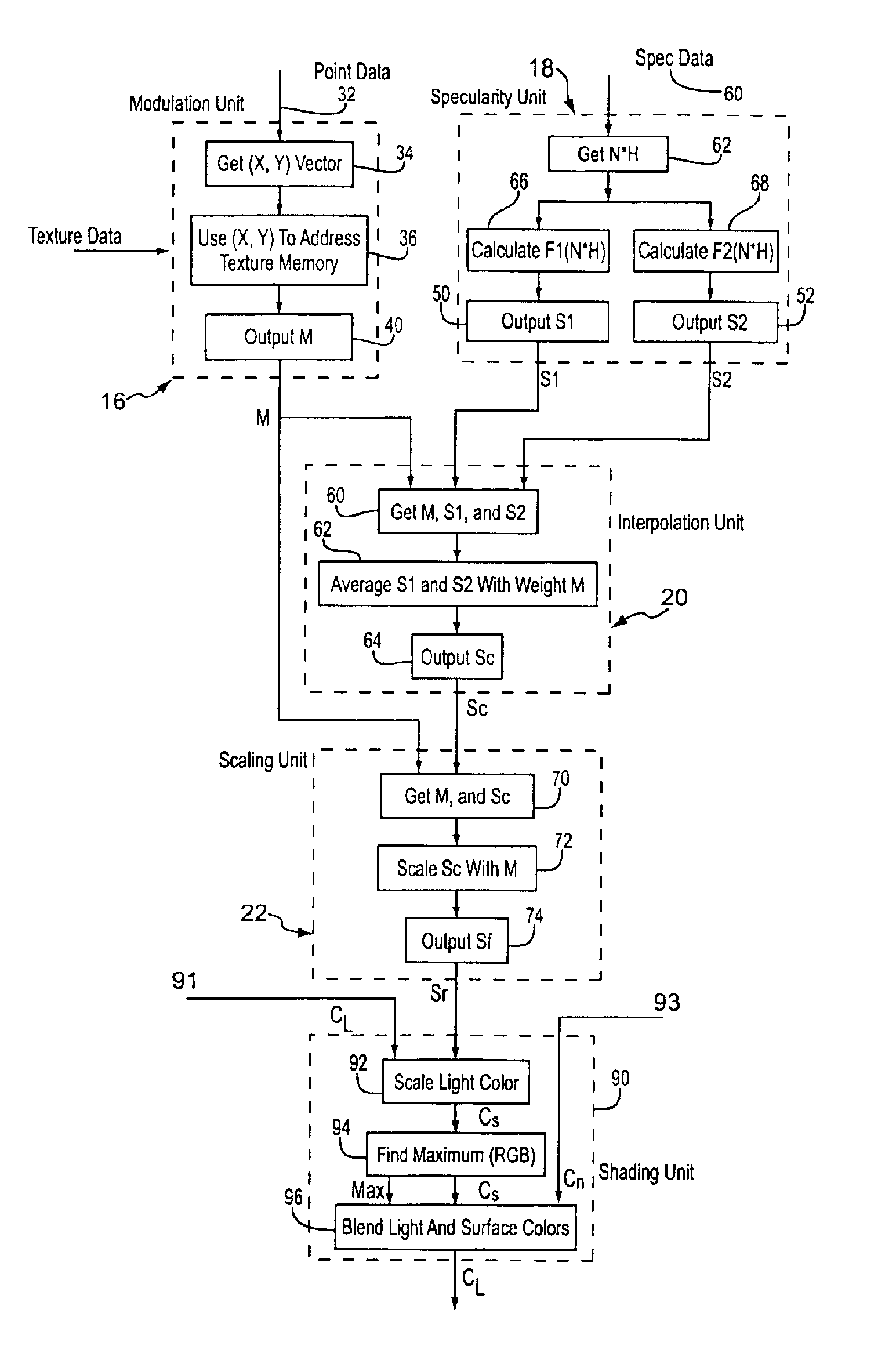
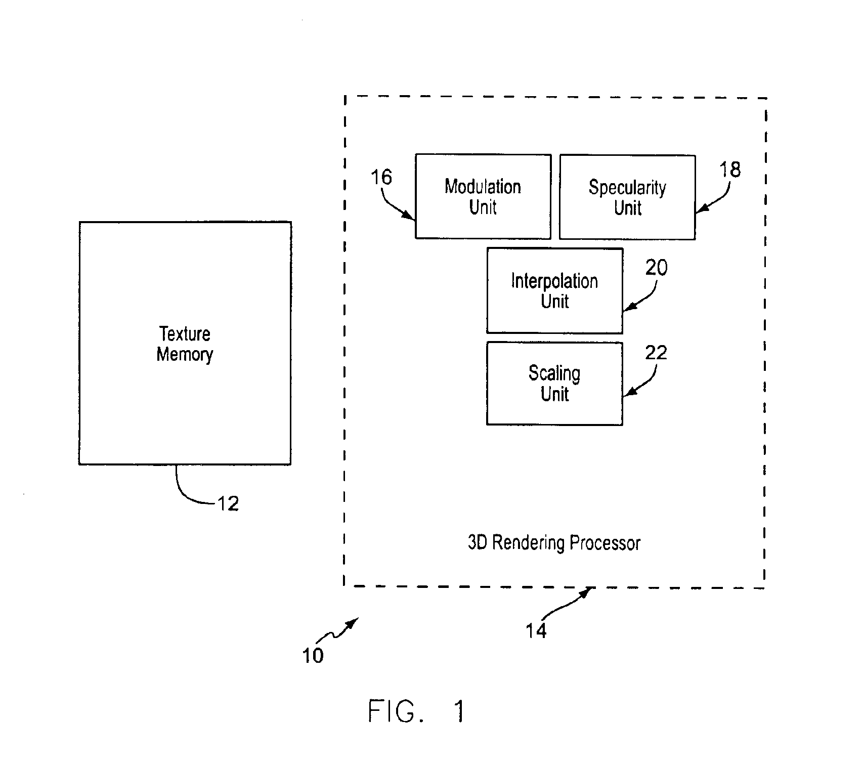
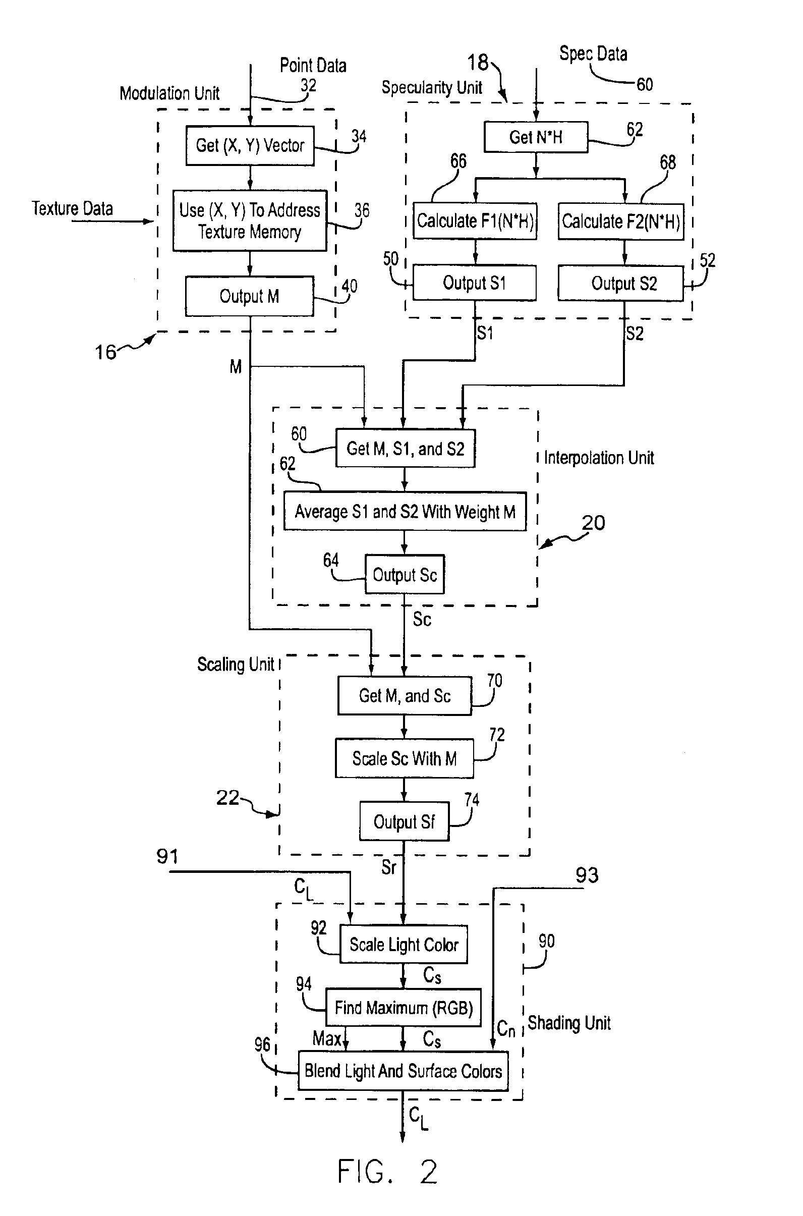
[0016]FIG. 1. gives an overview of a preferred hardware embodiment of a realtime 3D graphics system 10 in accordance with a preferred embodiment of the invention. The system includes: a texture memory 12 that contains one or more dirt maps; a modulation unit 16 which obtains a sp...


PUM


Abstract

A method and system for map based per-pixel specularity modulation of a surface in a real time 3D graphics renderer through the use of interpolated specularity function or environmental map values. One or more functional modules calculate a pair of specular light intensity values or color values. Each specularity value is representative of the specular light reflected by the given pixel at an extreme surface reflectance characteristic, i.e. one may represent reflection from a very smooth surface while the other represents reflection from a very rough surface. A specularity modulation, or dirt map, value is arrived at by either a procedural calculation based on surface offset coordinates or by retrieval from a two-dimensional map contained in a texture memory. The specularity modulation value is then used as a weight to interpolate the pair of specularity values. The resulting interpolated specularity value is then optionally scaled by the modulation value (or a derivative thereof) to produce a final specularity value. This final specularity intensity or color value is then passed to a lighting unit that modulates pixel color appropriately to include the given specular light.

Description

BACKGROUND OF THE INVENTION[0001]The present invention relates generally to the creation of computer generated images for viewing on a display screen. In particular, the present invention relates to the shading of 2-dimensional and 3-dimensional computer generated images.[0002]A primary motivation in the areas of shading and lighting in 3-dimensional computer graphics is to provide the viewer with a more realistic experience by accurately depicting the effects of light on surface variations. Lighting and shading in commercially available 3-dimensional graphics accelerators has traditionally been limited to a relatively simple vertex light variation scheme wherein light calculations are made for each polygon vertex and the resulting color values are interpolated throughout the drawn polygon surface. The limitations of Gouraud interpolation techniques such as these are well known and include inaccurate highlights and representation of only uniform surface variations at polygon vertice...

Claims


Application Information

Patent Timeline
IPC IPC(8): G06T17/00
CPCG06T15/04G06T15/506G06T15/50
Inventor COLLODI, DAVID J.
Owner CCVG
Why Eureka
Try Eureka