
Method for inserting objects into a working area in a computer application

a computer application and working area technology, applied in the direction of instruments, specific program execution arrangements, program control, etc., can solve the problems of non-working objects, non-working programs, tedious error searching, etc., and achieve the effect of simplifying the procedur

Inactive Publication Date: 2006-07-04
ACTCON CONTROL
View PDF47 Cites 9 Cited by
  • Summary
  • Abstract
  • Description
  • Claims
  • Application Information

AI Technical Summary

Benefits of technology

[0010]A first object of the present invention is therefore to provide a method for inserting an object into a working area on a computer screen, that simplifies the procedure.
[0012]A third object of the present invention is to provide a method for inserting an object into a working area on a computer screen, wherein the problem of attempting to make invalid insertions is avoided.

Problems solved by technology

Inserting an object into a location where it is not ment to be located may result in a non-working object, or even in a non-working program, with tedious error searching as a result.
However, the user then finds him / herself in a situation where the intended operation is impossible to perform, e.g. the object he / she intends to insert into a certain location is refused by the application.
This is frustrating, especially as the user does not obtain information regarding why the object cannot be inserted, nor regarding what object can be inserted instead.
An even larger problem with known methods for inserting objects of different types into a working area is the fact that the cursor always needs to be moved between the icons or menus from which the object type is chosen, and the desired location.
Another problem is the icons or menus themselves.
If menus are used, it can be difficult to quickly find the desired object type.
If icons are used they normally provide a better overview, but instead they take up valuable space that is needed for other purposes.

Method used


Image

  • Method for inserting objects into a working area in a computer application
  • Method for inserting objects into a working area in a computer application
  • Method for inserting objects into a working area in a computer application

Examples


Embodiment Construction

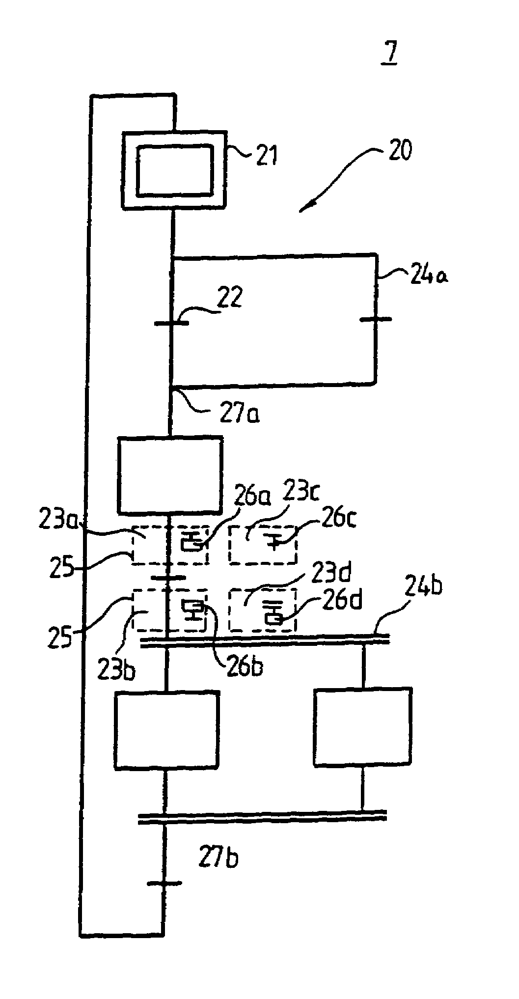
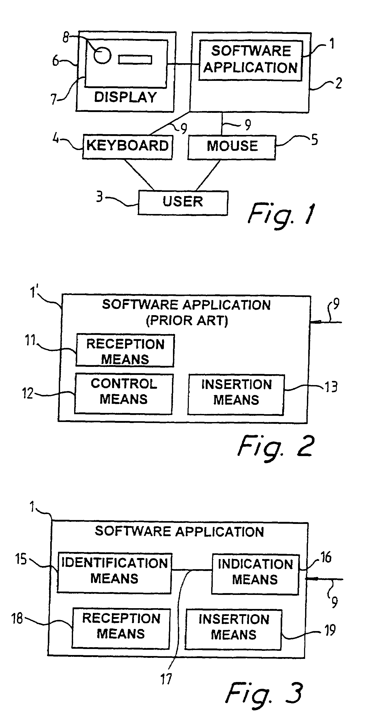
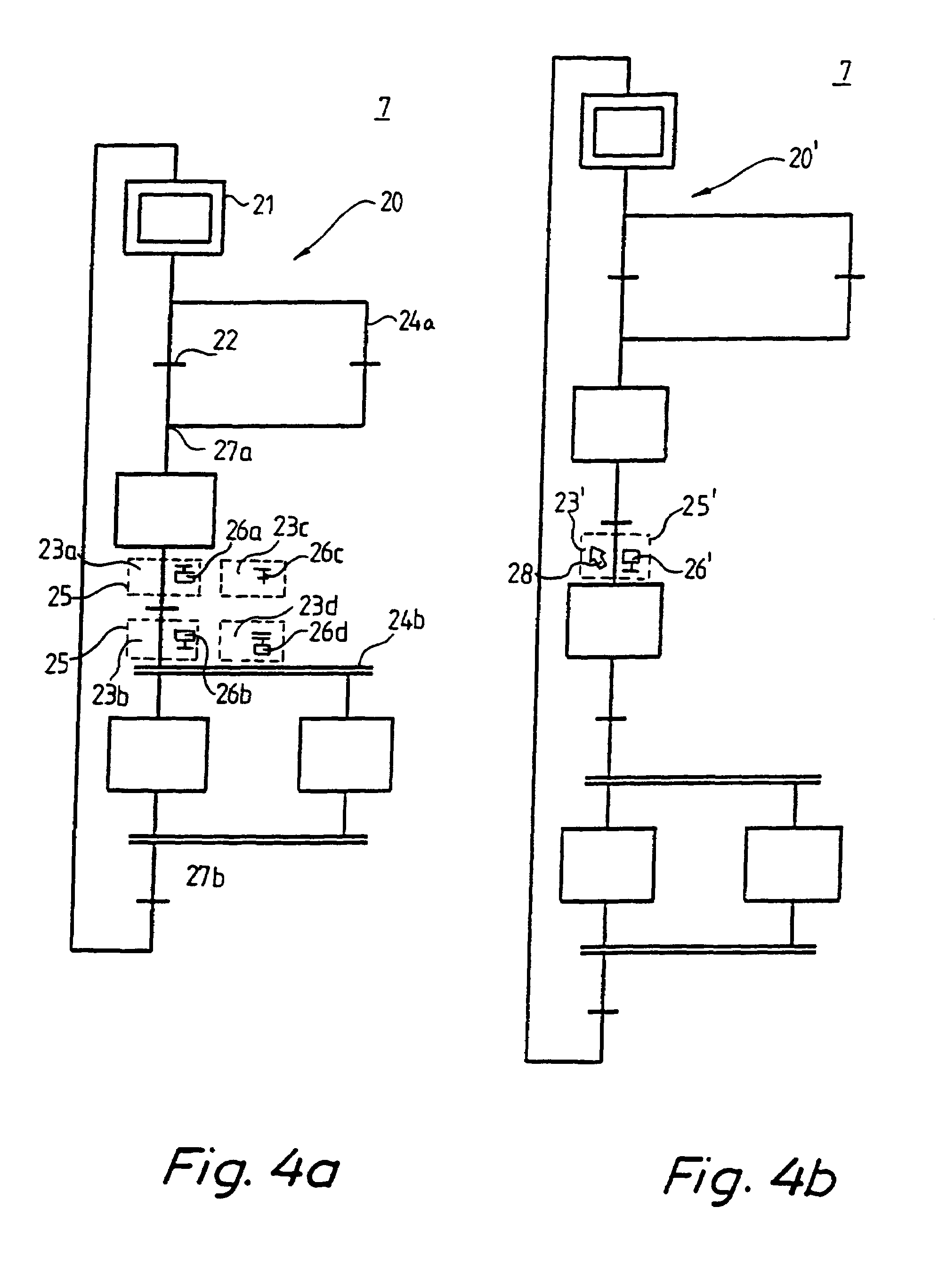
[0035]FIG. 1 illustrates an environment in which the method according to the invention can be utilized. A software application 1, e.g. a programming tool, is installed and running on a computer 2. A user 3 interacts with the application 1, giving instructions 9 to the software application through a keyboard 4 and with a pointing means, preferably a mouse 5. The application presents the results of the user's actions on a display unit, preferably a monitor 6, displaying to the user a working area 7, where operations corresponding to said actions are performed. Said operations may include inserting objects 8 into the working area 7, where they represent for example program actions or physical events.

[0036]FIG. 2 shows a software application 1′ according to prior art, suited for the insertion of objects into a working area. Said application 1′ typically includes means 11 for receiving input from the user, means 12 for deciding how to respond to the input from the user, and means 13 to i...


PUM


Abstract

The present invention relates to a method for facilitating the insertion of an object in a working area on a computer display, and is implemented in a computer application software. The method comprises the steps of indicating at least one subarea of the working area where an object is insertable, indicating an object type in association with each subarea, an object of said object type being insertable in said subarea, receiving input from the user selecting one of the at least one subarea, and inserting in the selected subarea an object of the type that is indicated at the selected subarea. Through this method, the user only needs to provide one single piece of input in order to insert an object in a valid location in a working area.

Description

[0001]This application is the national phase under 35 U.S.C. § 371 of PCT International Application No. PCT / SE98 / 02183 which has an International filing date of Nov. 30, 1998, which designated the United States of America and was not published in English.TECHNICAL FIELD[0002]The present invention relates to a method for fascilitating the insertion of an object into a working area on a computer display, said method being implemented in a computer application software and comprising the step of receiving input from the user selecting where on the screen an object of a previously specified object type is to be inserted.BACKGROUND ART[0003]In numerous computer applications, objects are selected by a user and inserted into an area of a computer display. This is especially frequent in different kinds of programming and designing, where objects belonging to several different object types are available to the user for insertion into a working area, such as a worksheet, a document, or any ot...

Claims


Application Information

Patent Timeline
IPC IPC(8): G09G5/00G06F9/45G06F3/0484G06F9/44
CPCG06F9/4443G06F3/04845G06F9/451
Inventor TERNULF, YNGVEPOURMAKHDOMI, SHAHRAMOTREUS, FINN
Owner ACTCON CONTROL
Learn More