Communication using bi-directional LEDs

a technology of leds and optical communications, applied in the field of light-emitting diodes, can solve the problems of increasing the cost and complexity of the communication system, and the difficulty of accurately controlling the voltage applied directly across the led to achieve the desired curren

Inactive Publication Date: 2006-07-04
MITSUBISHI ELECTRIC RES LAB INC
View PDF4 Cites 117 Cited by
  • Summary
  • Abstract
  • Description
  • Claims
  • Application Information

AI Technical Summary

Problems solved by technology

Because the current-voltage characteristic is exponential, it is difficult to control a voltage applied directly across an LED accurately enough to attain a desired current.
This increases the cost and complexity of the communications system.

Method used


Image

  • Communication using bi-directional LEDs
  • Communication using bi-directional LEDs
  • Communication using bi-directional LEDs

Examples


Embodiment Construction

Dual Pin LED Data Transceiver

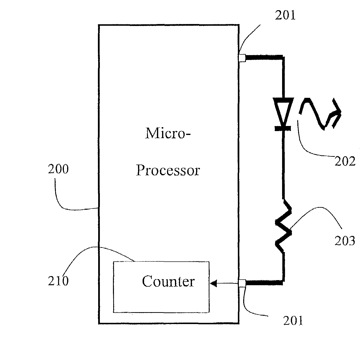
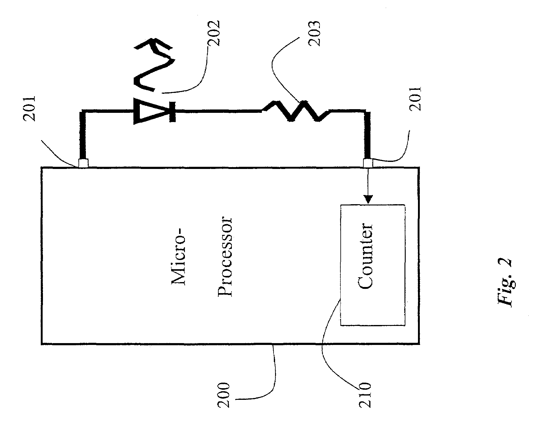
[0018]FIG. 2 shows an LED emitter / detector circuit according to the invention. Here, an LED 202 and resister 203 are coupled in series between two I / O pins 201 of a microprocessor or microcontroller 200. Now both ends of the LED / resistor circuit 202-203 are connected to the microprocessor 200. The I / O pin can be set low (0V), high (5V), or the pin can be used as an input, using conventional programming techniques.

Operating Modes

[0019]FIGS. 3a–c show how this circuit can operate in three modes, forward bias or “light,” not forward bias or “reverse bias” and “discharge,” or sense respectively. In the light mode of FIG. 3a, the LED operates conventionally and emits light. The emitted light can be modulated to transmit data. In reverse bias mode of FIG. 3b, the normal emitting polarities are switched to reverse bias the junction of the diode. By then releasing one end in discharge mode of FIG. 3c, i.e., setting that end to be an input to the microprocessor, ...


PUM

PropertyMeasurementUnit
forward voltageaaaaaaaaaa
voltageaaaaaaaaaa
capacitanceaaaaaaaaaa

Abstract

An optical communications transceiver includes an LED coupled in series with a resistor. A microprocessor has one I/O pin connected to the LED. In a first mode or transmit mode, the LED is periodically driving in forward bias to emit light to transmit data. In a second or receive mode, the LED is periodically not driven in reverse bias, e.g., reverse bias or zero bias. Then, the LED is allowed to change charge of the capacitance of the LED's junction using a photo-current. The change in charge is measured using a timer. When the change in charge exceeds a predetermined threshold, input light is sensed. Thus, the LED can be used to receive data in the second mode.

Description

RELATED APPLICATION[0001]This application is a continuation-in-part application of U.S. patent application, Ser. No. 10 / 115,299 now U.S. Pat. No. 6,664,744 “Automatic Backlight for Handheld Devices,” filed by Dietz on Apr. 3, 2002.FIELD OF THE INVENTION[0002]This invention relates generally to light emitting diodes (LEDs), and more particularly to LEDs used for bi-directional optical communications.BACKGROUND OF THE INVENTION[0003]Light emitting diodes (LEDs) are inexpensive and widely used as light sources. Their diverse applications include numeric displays, flashlights, liquid crystal backlights, vehicle brake lights, traffic signals, backlights, and the ubiquitous power-on indicator light on almost every electronic device, and modern electrical appliance.[0004]Because LEDs are most often used as light emitters, it is easy to forget that they can also operate as photodiodes, i.e., light detectors. Although most LEDs are designed as light emitters, and not light detectors, all LED...

Claims


Application Information

Patent Timeline
Patent Type & Authority Patents(United States)
IPC IPC(8): H04B10/00G02F1/133G09G3/14G09G3/32G09G3/34H01L33/00H04M1/22H04M1/73H05B37/02
CPCG09G3/3406H04M1/22G09G3/14G09G3/32H04W52/027G09G2360/144H01H2219/038G09G2320/0626Y02D30/70
Inventor DIETZ, PAUL H.YERAZUNIS, WILLIAM S.LEIGH, DARREN L.VANNUCCI, GIOVANNI
Owner MITSUBISHI ELECTRIC RES LAB INC
Why Eureka
Try Eureka