Eureka AIR delivers breakthrough ideas for toughest innovation challenges, trusted by R&D personnel around the world.

Strategies for locomotive operation in tunnel conditions

Active Publication Date: 2006-07-04
GE GLOBAL SOURCING LLC
View PDF9 Cites 68 Cited by
  • Summary
  • Abstract
  • Description
  • Claims
  • Application Information

AI Technical Summary

Benefits of technology

The present invention is a system and method for configuring and reconfiguring multiple locomotives in a train as it passes through a confined area, such as a tunnel. The system and method provide dynamic responses to changes in tunnel conditions and allow for efficient operation of the train. The invention can determine when the locomotives enter a tunnel, even without position information, and quickly return them to a desired level of operation upon exiting the tunnel. The system and method can operate over a wide range of conditions and can even adapt to unexpected conditions within the tunnel. The technical effects of the invention include improved efficiency of train operations and reduced risk of engine damage during passage through a tunnel.

Problems solved by technology

The system and method operate over a wide range of conditions including the fact that tunnel entrance information may not always be available, or that conditions within a tunnel may not be as expected, particularly when other trains have recently passed through the same tunnel depleting available oxygen within the tunnel and raising the temperature within the tunnel.

Method used


Image

  • Strategies for locomotive operation in tunnel conditions
  • Strategies for locomotive operation in tunnel conditions
  • Strategies for locomotive operation in tunnel conditions

Examples


Embodiment Construction

[0021]The following detailed description illustrates the invention by way of example and not by way of limitation. The description clearly enables one skilled in the art to make and use the invention, describes several embodiments, adaptations, variations, alternatives, and uses of the invention, including what is presently believed to be the best mode of carrying out the invention.

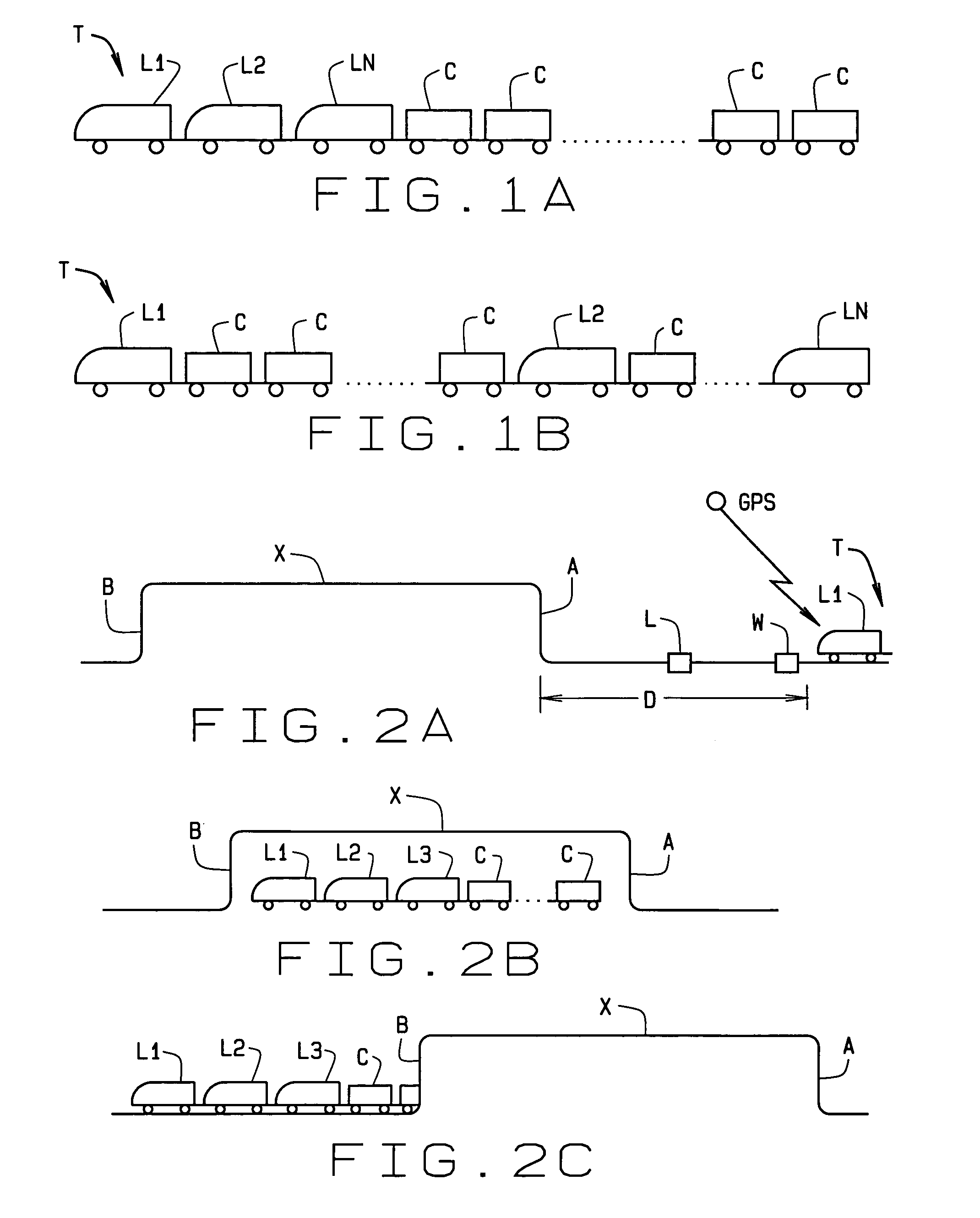
[0022]The present invention is directed to passage of a train T through a tunnel X, or a snow shed (not shown) or environmental restrictive area (also not shown). For convenience, throughout this description and the accompanying claims, the term tunnel shall also be meant to include snow sheds and other environmental restrictive areas where a locomotive may be deprived of combustion air and / or cooling.

[0023]The train has multiple locomotives L1-Ln as previously described. The system and method of the invention can be separated into three phases:

[0024]First, because it is known that conditions within the c...


PUM


Abstract

A method of controlling operation of a train (T) for passage of the train through a tunnel. The train has a plurality of locomotives (L1-Ln) pulling the train. The position of the lead locomotive relative to the tunnel entrance is determined, as is the amount of time before the train enters the tunnel. Each locomotive is separately configured for passage through the tunnel as a function of performance characteristics of the locomotive and the locomotive's current operating status, as the train approaches the tunnel. Once the train enters the tunnel, the performance characteristics of each locomotive are continually monitored. The performance requirements for one or more of the locomotives are then dynamically changed as a function of conditions within the tunnel and the current performance characteristics of each locomotive. This is done to maintain a sufficient combined performance capability from the locomotives to move the train through the tunnel. Upon exiting the tunnel, the locomotives' full operating capabilities are quickly restored by enhancing their thermal recoveries.

Description

CROSS-REFERENCE TO RELATED APPLICATIONS[0001]None.STATEMENT REGARDING FEDERALLY SPONSORED RESEARCH OR DEVELOPMENT[0002]Not Applicable.BACKGROUND OF THE INVENTION[0003]This invention relates to operation of a plurality (consist) of locomotives used to pull a train of cars; and, more particularly, to configuring the locomotives prior to entering a confined area such as a tunnel, snow shed, or other environmental restrictive area which may deprive a locomotive of combustible air and effect cooling of a locomotive's engine. It further relates to operation of the locomotives during passage through the tunnel, shed or area, and recovery of the engine upon exiting the tunnel, shed or area.[0004]Referring to FIGS. 1A and 1B, a train T is shown to include a number of engines or locomotives L1-Ln for pulling a train of cars C. The number of locomotives required is a function of the weight of the cars comprising the train and the tonnage of the lading they carry. In FIG. 1A, the locomotives ar...

Claims


Application Information

Patent Timeline
Patent Type & Authority Patents(United States)
IPC IPC(8): G05D1/00G05D3/00B61L3/12B61L15/00B61L23/04
CPCB61L3/006B61L15/0081B61L25/026Y02T10/7258B61L2205/04Y02T10/72B61L15/0058
Inventor ARMBRUSTER, ROBERT A.DAUM, WOLFGANGBRANKA, SCOTT M.ISZKULA, CARLLAWRY, BRIAN
Owner GE GLOBAL SOURCING LLC
Why Eureka
Eureka Blog
Learn More