Knife assembly

a knife and assembly technology, applied in the field of knife assembly, can solve the problems of expensive welding knife assemblies and the need to replace the entire uni

Inactive Publication Date: 2006-07-11
JENSEN RALIEGH J
View PDF11 Cites 45 Cited by
  • Summary
  • Abstract
  • Description
  • Claims
  • Application Information

AI Technical Summary

Problems solved by technology

Welded knife assemblies are expensive and the entire unit must be replaced when even a single blade is damaged or dulled.

Method used


Image

  • Knife assembly
  • Knife assembly
  • Knife assembly

Examples


Embodiment Construction

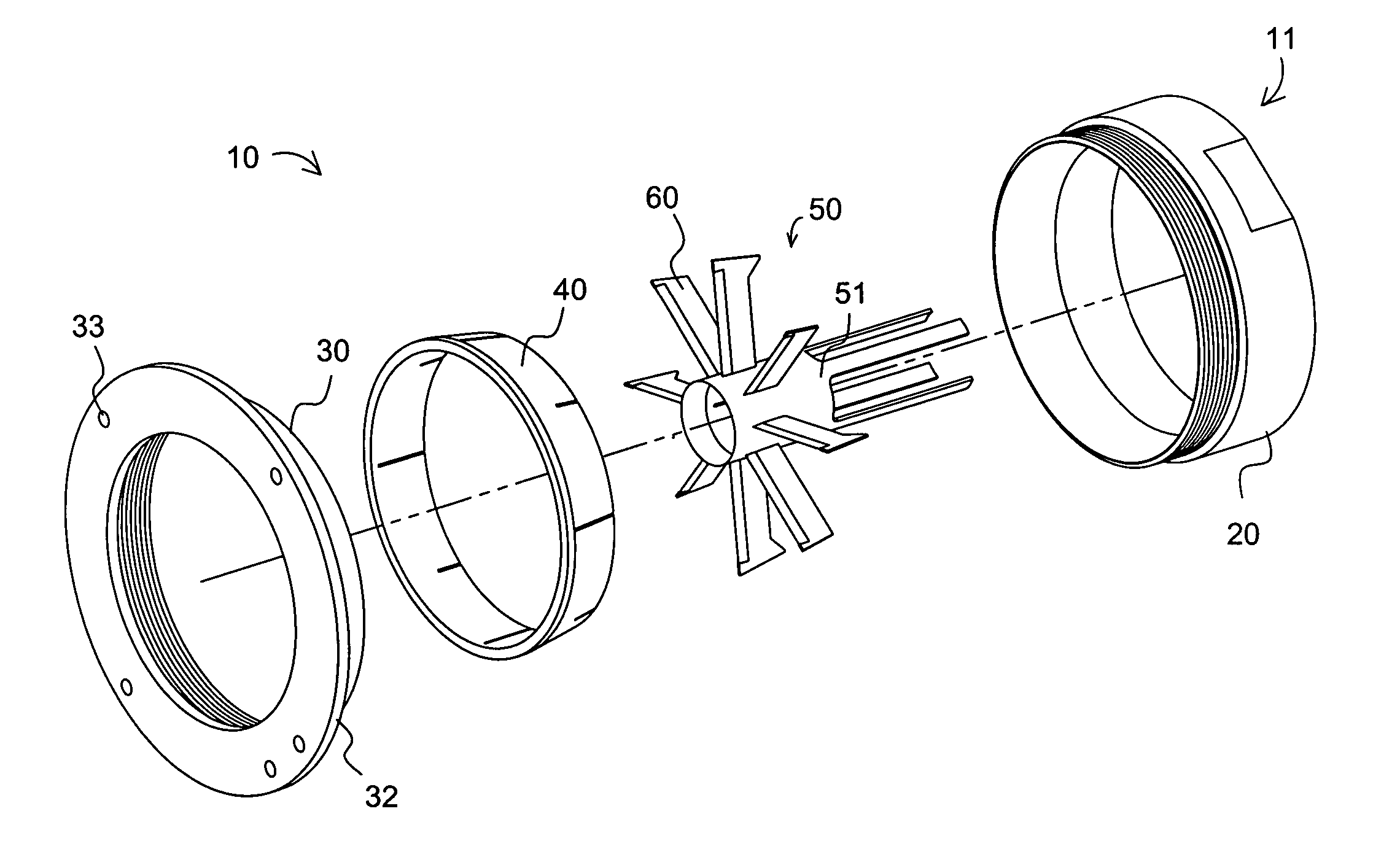
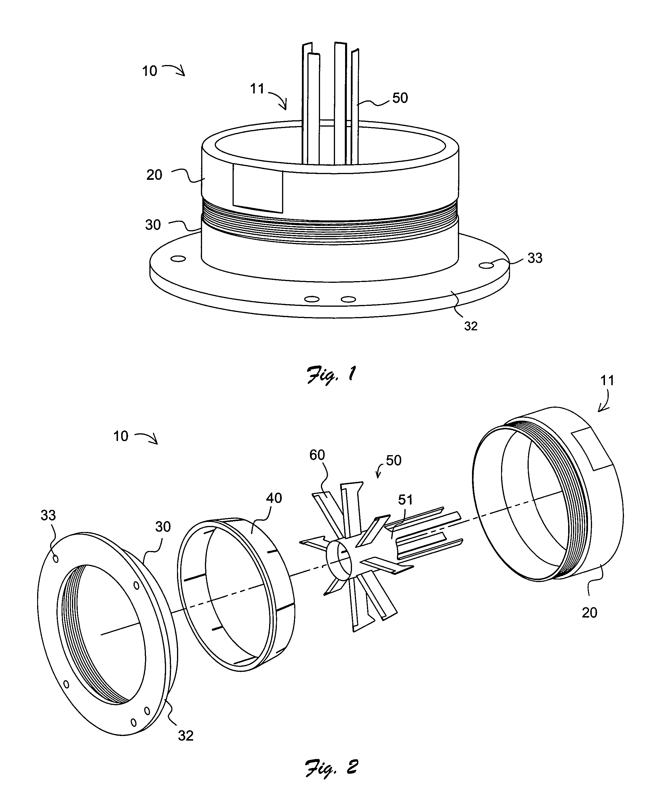
[0018]Referring to FIGS. 1, 2 and 5–7, a first preferred embodiment of knife assembly 10 for cutting food product, for instance fruits such as apples, is shown to advantage. Compression ring 20 is shown engaging base ring 30. Core knife 50 is positioned within aperture 11 of knife assembly 10. Base ring 30 includes mounting flange 32 having a plurality of apertures 33 formed through a cross-section of mounting flange 32 permitting one or more points of attachment between knife assembly 10 and a cutting apparatus, (not shown). FIG. 2, 5 and 6 show a plurality of blades 60 connected to and extending between core knife 50 and blade support ring 40. The plurality of blades 60 may include two or more blades arranged radially about core knife 50. In the preferred embodiment pairs of blades 60 oppose one another. The plurality of blades 60 preferably equals an even number. The plurality of blades 60 may be stacked in vertical tiers, (not shown), or in the alternative, may be arranged about...


PUM

PropertyMeasurementUnit
mechanicalaaaaaaaaaa
compressive forceaaaaaaaaaa
sizeaaaaaaaaaa

Abstract

A knife assembly for use in a food cutting apparatus includes a compression ring adapted for threaded engagement with a base ring. The compression ring includes a threaded collar that tapers thinner towards its leading edge. The blade support ring tapers thinner towards a leading edge of the support ring sidewall. The blade support ring includes a sidewall having a plurality of blade second end receiving slots. At least two blades are connected at their first ends to a central cutter element and at their second ends to the blade support ring. As the compression ring engages the base ring, the advancing and opposing surfaces of the tapered sidewall of the compression ring and the tapered sidewall of the blade support ring cooperate imparting a compressive force against the ends of the blades, securing the blade with respect to the compression ring and the cutter element.

Description

BACKGROUND OF THE INVENTION[0001]1. Field of Invention[0002]This invention relates to the cutting of food product and more particularly to a knife assembly for cutting food product.[0003]2. Background of the Invention[0004]Devices for cutting food products into slices are well-known in the art and may include an array of cutting knives with a means to propel or impinge the food product through or against the knife array. The food product may be conveyed through a knife assembly by entraining it in a fluid stream. Alternately, the food product may be forced against the knife array by mechanical or other means.[0005]The prior art of food cutting knife assemblies includes both fixed relatively rigid knives, see for instance U.S. Pat. Nos. 5,095,794, 5,009,141, and tensioned blades, see for instance U.S. Pat. Nos. 5,343,623 and 6,601,491. These devices have commonly been employed to cut a food product, typically potatoes into sticks or french fries. While a variety of devices have been ...

Claims


Application Information

Patent Timeline
Patent Type & Authority Patents(United States)
IPC IPC(8): B26B3/03B26B3/04
CPCB26D1/0006B26D2001/004B26D2001/0033B26D3/26Y10T83/6472Y10T83/937Y10T83/9493Y10T83/9498
Inventor JENSEN, RALIEGH J.
Owner JENSEN RALIEGH J
Why Eureka
Try Eureka