Drying device

a technology of drying device and drying medium, which is applied in the direction of drying machine with progressive movement, photosensitive materials, instruments, etc., can solve the problems of increased production cost, irregular dry condition of material, jerky transport, etc., and achieves small aperture rate, smooth transport of recording medium, and large aperture rate

Inactive Publication Date: 2006-07-11
FUJIFILM CORP +1
View PDF7 Cites 20 Cited by
  • Summary
  • Abstract
  • Description
  • Claims
  • Application Information

AI Technical Summary

Benefits of technology

[0007]An object of the present invention is to provide a drying device that prevents irregular dry condition of a photosensitive material and offers smooth transport of the photosensitive material.
[0010]Therefore, in those zones where the internal pressure of the dry air blowing component is high, the velocity of dry air is high, but the aperture rate is small. Comparatively, in those zones of the dry air blowing component where the internal pressure is lower, the velocity dry air is slower and the aperture rate is larger. As a result, it is possible to make the volume of blown dry air per unit area almost even throughout an external surface of the dry air blowing component. Because this allows dry air to evenly blow to a surface of a recording medium, the recording medium is dried evenly without any irregular dry condition. Moreover, evenness of dry air to the surface of the recording medium enables pressing the recording medium onto a conveyer mechanism with a uniform force, and guarantees smooth transport of the recording medium while preventing it from slipping on the conveyer mechanism.
[0011]Chamfering the internal periphery of each individual dry air outlet of the dry air blowing member on its external side, i.e. on its paper path side, prevents an edge of the recording medium from being caught in the internal periphery of the dry air outlet, even if the recording medium curls because of some reasons including over-dryness.

Problems solved by technology

This system, however, needs plural cylinders and a lot of nipping rollers, which increases the number of components and production cost.
In the drying device used in the latter prior art, however, the volume of dry air blown from dry air outlets to the photosensitive material is so uneven that it sometimes caused irregular dry condition in the material or jerky transport of the material because curled edges were caught in the outlets.

Method used


Image

  • Drying device
  • Drying device
  • Drying device

Examples


Embodiment Construction

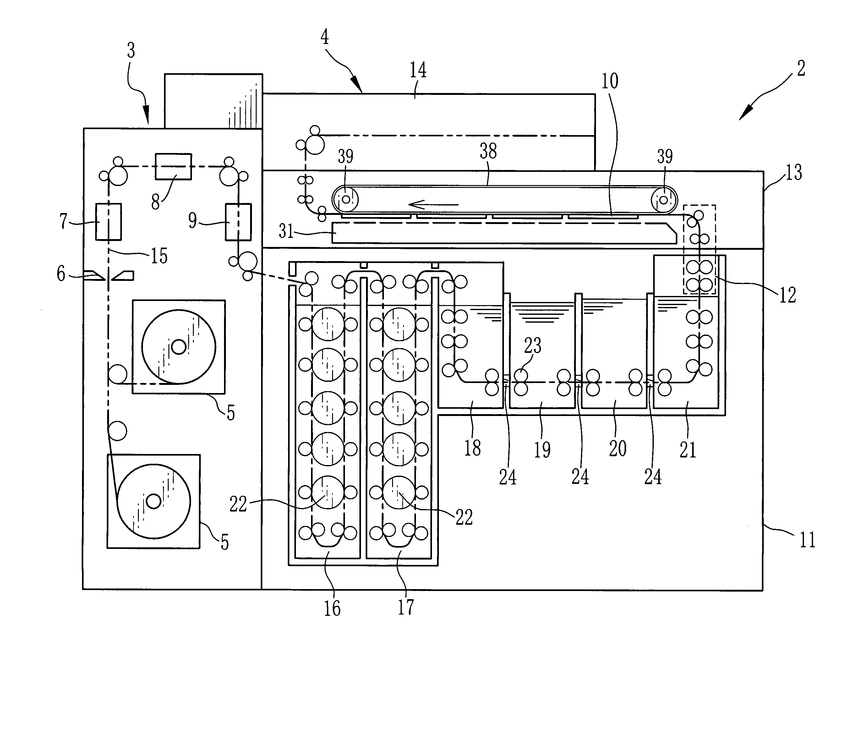
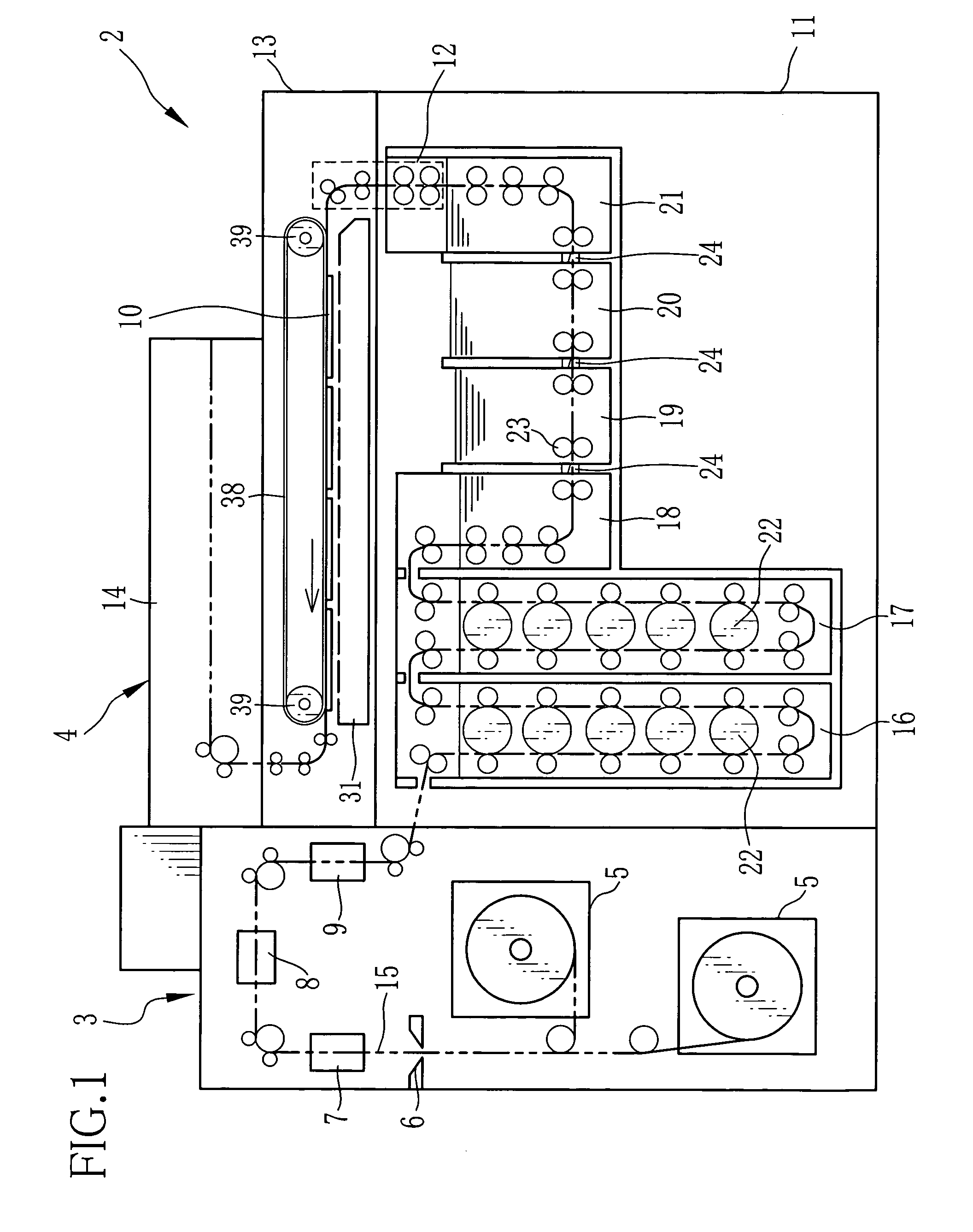
[0019]As FIG. 1 shows, a printer processor 2 consists of a printer section 3 and a processor section 4. The printer section 3 has a magazine 5, a cutter 6, a back printing section 7, an exposure section 8 and a distribution section 9. A web of photosensitive material set in the magazine 5 is cut by the cutter 6 according to a size of photo prints into cut sheets of the photosensitive material 10. The photosensitive material 10 is printed on its back side a frame number and corrected data at the back printing section 7 on its way to the exposure section 8 along a paper path 15 in FIG. 1. The exposure section 8 carries out exposure recording of images based on image data on a light-receptive surface of the photosensitive material 10. The exposed photosensitive material 10 is then distributed into some rows at the distribution section 9 and conveyed to the processor section 4.

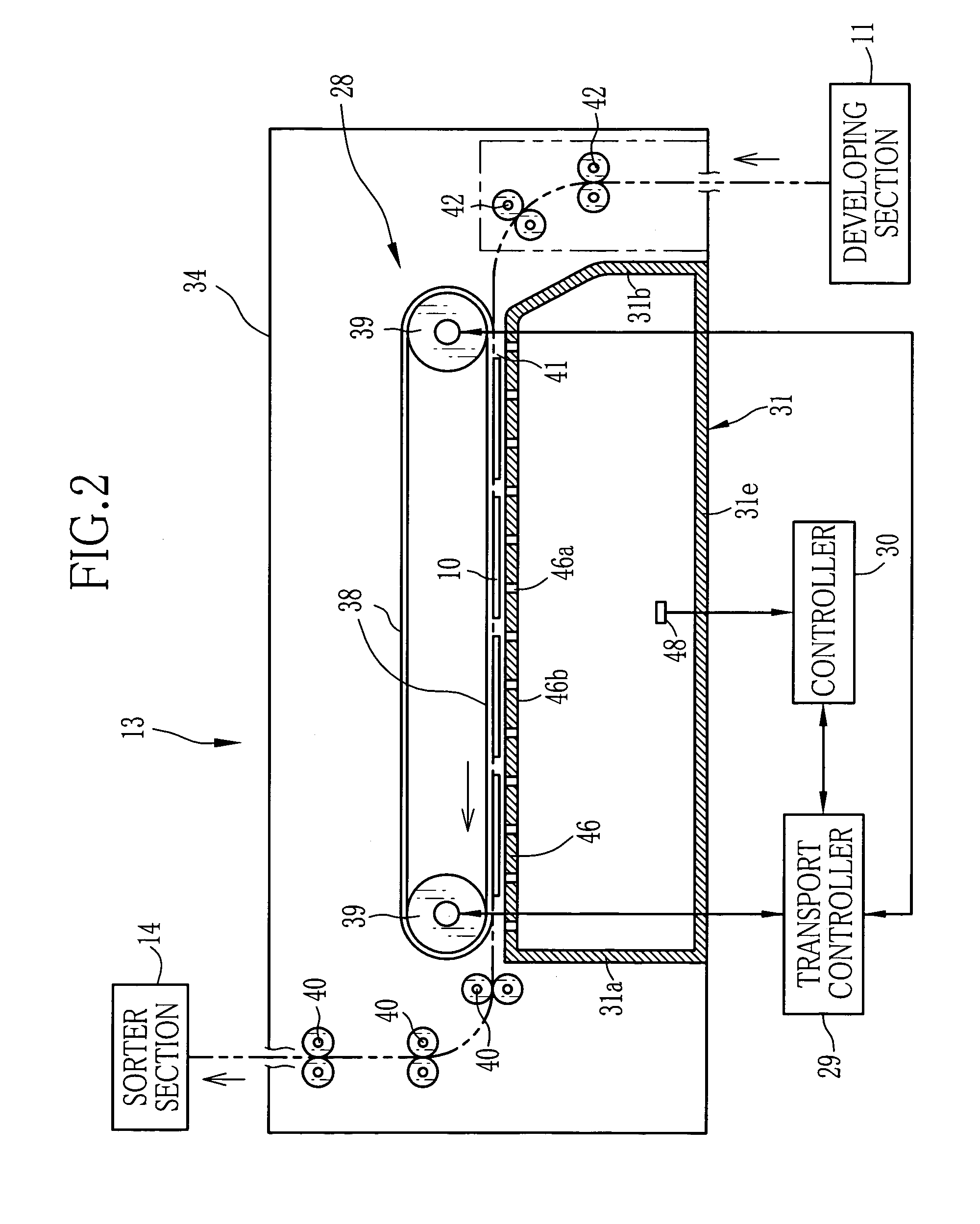
[0020]The processor section 4 has a developing section 11, a squeezing section 12, a dry section 13 and a sorte...


PUM


Abstract

In a dry air blowing plate, rows of dry air outlets are arranged at given intervals in a transport direction of a photosensitive material. The interval between the dry air outlets within the row is narrower in a front zone of the dry air blowing plate that is close to a dry air inlet, whereas the interval is wider in a rear zone of the dry air blowing plate that is away from the dry air inlet. In the front zone, the velocity of dry air is lower but the aperture rate per unit area is larger. On the other hand, in the rear zone, the velocity of dry air is higher but the aperture rate is smaller. As a result, the volume of blown dry air is almost the same throughout an external surface of the dry air blowing plate, so the dry air is evenly blown to a surface of a photosensitive material.

Description

FIELD OF THE INVENTION[0001]The present invention relates to a drying device that dries a recording medium, especially a photosensitive material after going through photo-finishing solutions.BACKGROUND ART[0002]In the case of an automatic processor like a printer processor used to develop photo prints, a photosensitive material such as photographic printing paper is cut by a cutter according to a size of photo prints into a cut-sheet photosensitive material, on which photo printing is done. After the printing process, the photosensitive material is distributed into single line or plural lines at a distribution section and then conveyed to a developing section. Generally, the developing section develops the photosensitive material by conveying it to processing tanks by conveyer rollers and by letting it pass through respective processing liquids one after another.[0003]The developed photosensitive material is wet with moisture from the tanks. For this reason, the developed photosensi...

Claims


Application Information

Patent Timeline
Patent Type & Authority Patents(United States)
IPC IPC(8): F26B13/06F26B13/04F26B13/10F26B13/20F26B15/18F26B21/12G03D15/02
CPCF26B13/103G03D15/022F26B15/18
Inventor YOSHIDA, FUTOSHI
Owner FUJIFILM CORP
Why Eureka
Try Eureka