Multi-stage oil pumping station

Inactive Publication Date: 2006-07-11
DAIMLER AG
View PDF12 Cites 2 Cited by
  • Summary
  • Abstract
  • Description
  • Claims
  • Application Information

AI Technical Summary

Benefits of technology

[0009]With the independent drives for the various oil pumps, any desired pump types as well as suction stages and compression stages can be combined in a common oil pumping system. Furthermore, the operating speeds of the different oil pumps are independently adjustable so that the pumping power of the system is very flexible and can be adjusted to very different operating conditions of a motor vehicle. In contrast to an arrangement in

Problems solved by technology

In contrast to an arrangement including several oil pumps arranged one after the other, also the risk that during operation or during assembly th

Method used


Image

  • Multi-stage oil pumping station
  • Multi-stage oil pumping station

Examples


Embodiment Construction

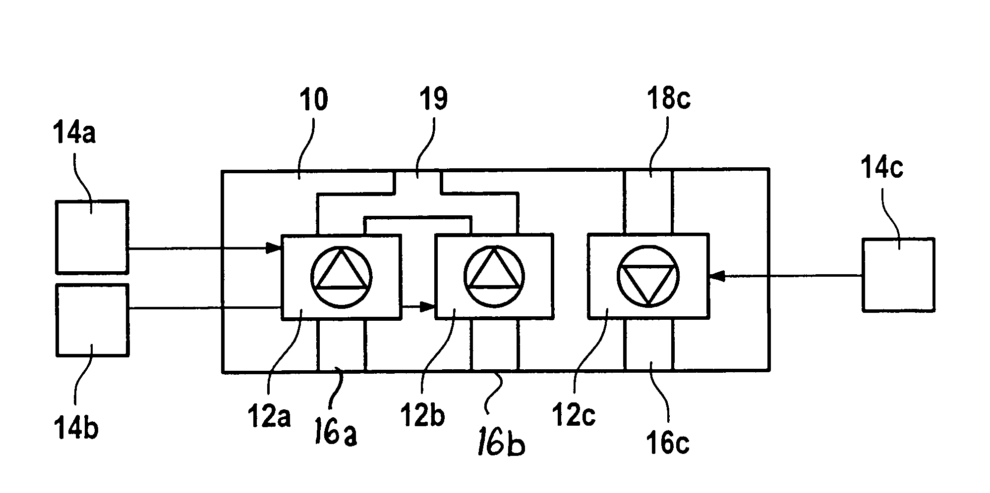
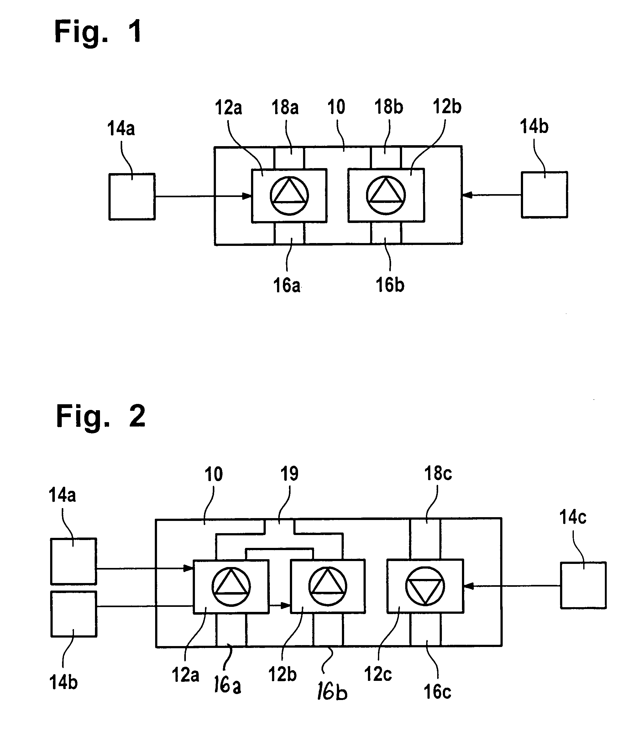
[0017]FIG. 1 shows in a highly simplified representation a first embodiment of a multi-stage oil pumping system which is used advantageously in an oil supply system of a motor vehicle.

[0018]The multistage oil pumping system comprises a housing 10 in which two oil pumps 12a and 12b are arranged in axial side-by-side relationship. As oil pumps 12a, 12b ring gear pumps, spur gear pumps, wing cell pumps or similar pumps may be used, wherein the two oil pumps 12a and 12b of the oil pumping system may be of the same type as well as different types of pumps. Furthermore, the oil pumps 12 and 12b may be controllable pumps or constant volume pumps.

[0019]Each of the oil pumps 12a and 12b of the oil pumping system includes its own drive 14a and, respectively 14b, by which the oil pumps are driven independently of each other. The drives 14a, 14b may include chain drives, gear drives, belt drives or similar. In addition, the two oil pumps 12a and 12b may have a common drive plane or their drive ...


PUM


Abstract

In a multistage oil pumping system for an oil supply system of a motor vehicle comprising at least two oil pumps arrange axially in side-by-side relationship, each of the oil pumps is connected to a separate drive so that the oil pumps can be operated independently of one another.

Description

BACKGROUND OF THE INVENTION[0001]The invention relates to a multi-stage oil pumping system for an oil supply system of a motor vehicle including at least two oil pumps arranged axially adjacent one another.[0002]In modern motor vehicles, the oil supply systems generally need several oil pumps or, respectively, oil pumping stages in which several pumps of the same type or different types of pumps are combined for supplying lubricating oil to various motor components.[0003]DE 195 02 235 A1, for example, discloses an oil supply for a motor vehicle with a two-stage oil pumping system, wherein, in addition to a controllable pump, a constant volume pump is provided and both pumps are driven by a common drive shaft, the pumping direction of the controllable pump being changeable. This known two-stage oil pumping system is unusable for engines of different size because of its pumping characteristics.[0004]The various oil pumps of a multi-stage oil pumping systems are often arranged serially...

Claims


Application Information

Patent Timeline
IPC IPC(8): F01M1/02F01M1/12
CPCF01M1/02F01M2001/123F01M2001/0253F01M2001/0207
Inventor BRUHL, REINHOLDDOLL, ROLANDWEINERT, FRANK
Owner DAIMLER AG
Why Eureka
Try Eureka