Linear drive metal forming machine

a metal forming machine and linear drive technology, applied in the field of container die necking, can solve the problems of difficult to develop the fine tuning properties required to manufacture containers with significant neck lengths, long necking profiles, and complicated trial and error processes, and achieve high degree of versatility in forming operations, high degree of adjustable, and rapid modification of metal forming.

Inactive Publication Date: 2006-07-11
CROWN PACKAGING TECH
View PDF7 Cites 48 Cited by
  • Summary
  • Abstract
  • Description
  • Claims
  • Application Information

AI Technical Summary

Benefits of technology

[0012]According to one form of the present invention, there is provided a method of reducing the diameter of a sidewall of a seamless unitary metal container body having a sidewall, an endwall at one end of the sidewall, an open end at an opposite end of the sidewall, and a longitudinal axis extending between the endwall and the open end. The method involves introducing a knockout element into the container body through the open end, providing a forming die shaped to reduce the diameter of the sidewall of the container body when the open end of the container body is forced therein to produce a neck portion of reduced diameter on the container body, driving the open end of the container body into the forming die, retracting the knockout element through the neck portion as the neck portion is formed, and removing the container body from the forming die and knockout element. The method utilizes at least one linear reciprocal prime mover arranged to create movement or force in the direction of the longitudinal axis of the container body to move the knockout element, or to force the container body into the forming die, or both.
[0014]The use of linear prime movers under computer numerical control for manipulating thin gauge metal offers a wide variety of advantages over conventional technology and is not limited to die necking. The present invention provides a high degree of versatility in forming operations and a capability to change profile shaping and a variety of operating parameters in real time. Cam development can be accomplished using the readily adjustable process of the present invention to derive empirical data quickly and efficiently with programmable adjustment of variables such as motion, force and velocity. Stroke length can be adjusted by simply dialing in the desired length on the fly and without shutting down operations as opposed to tearing the machine down, removing the cam that determines thrust, retooling the cam, replacing and testing the new stroke to determine if it matches the intended modification and finally to determine if the modification matches the intended result on the cam profile. A variety of forming variables and associated ratios can be customized and easily adjusted for individual operations and can be controlled independently for each stage in a multiple stage machine. The present invention allows forming operations that require a high degree of variability and precision to be possible. It also allows machinery to be developed which may have been impractical from a development standpoint using current technology.
[0015]In a particularly preferred form, the present invention may therefore comprise a method of reducing the diameter of the sidewall at the open end of a seamless unitary metal container body having a sidewall disposed about a longitudinal axis and a unitary endwall at one longitudinal end of the sidewall opposite to the open end comprising: placing the container body with the endwall in communication with a drive segment and the sidewall in communication with a forming segment having a fixed position forming die of curvilinear configuration in longitudinal cross section and located to form a juncture with the original diameter of the sidewall and progressing with further reduction in diameter toward the open end of the container body; driving a knockout ram with a first linear drive motor that produces a reciprocal motion in the longitudinal axis relative to the container; drawing a knockout that is connected to the knockout ram, the knockout disposed to engage an interior surface of the open end of the container and having a substantially uniform reduced diameter corresponding to the reduction in diameter at the curvilinear configuration of the forming die; extending the knockout longitudinally with the first linear motor to a depth within the open end of the container body beyond the juncture with the original diameter of the sidewall; driving a pusher ram with a second linear drive motor producing a reciprocal motion in the longitudinal axis relative to the container; engaging an exterior surface of the endwall of the container with a pusher pad that is driven by the pusher ram; transmitting a linear force by the second linear motor through the pusher ram to the pusher pad to the endwall of the metal container to the sidewall of the metal container thus forcing the sidewall into the curvilinear portion of the forming die; retracting the knockout while the linear force is being applied to the metal container during the die forming process; reducing the diameter of the sidewall that is contiguous to the open end of the unitary can body as the container reaches an endpoint of the curvilinear configuration within the forming die.
[0018]The present invention has numerous advantages over prior art. These include a high degree of versatility in forming operations and a capability to change operating parameters on the fly. Variables such as motion, force and velocity are programmable and highly adjustable at anytime during the forming stroke. In combination with this variability the present invention allows for alteration of the programming in real time, and thus, modifications to the metal forming can be accomplished rapidly and without shutting down or retooling the production equipment. This real time alteration of metal forming allows the apparatus to be utilized as a development tool to set manufacturing parameters on production machines that do not possess such variability.
[0019]The forming variables and associated ratios can be customized and easily adjusted for individual operations and can be controlled independently for each stage in a multiple stage machine. This can be accomplished on the “push” side of the forming operation and also on the “pull side” with the same or different forces. These additional motions can be used for multiple necking stages or any other operation that require linear motion such as expandable mandrels or for performance of other operations (i.e., bottom piercing etc.).

Problems solved by technology

There are practical limits on the reduction of the diameter of the material for any given material in any given die.
Conventional die necking of metal containers is accomplished with large-scale machinery that is very difficult to develop the fine tuned properties required to manufacture containers with significant neck length.
The development of necking profiles is currently a long, involved, trial and error process that can take months to establish the proper parameters for each necking stage necessary to produce longneck containers.

Method used


Image

  • Linear drive metal forming machine
  • Linear drive metal forming machine
  • Linear drive metal forming machine

Examples


Embodiment Construction

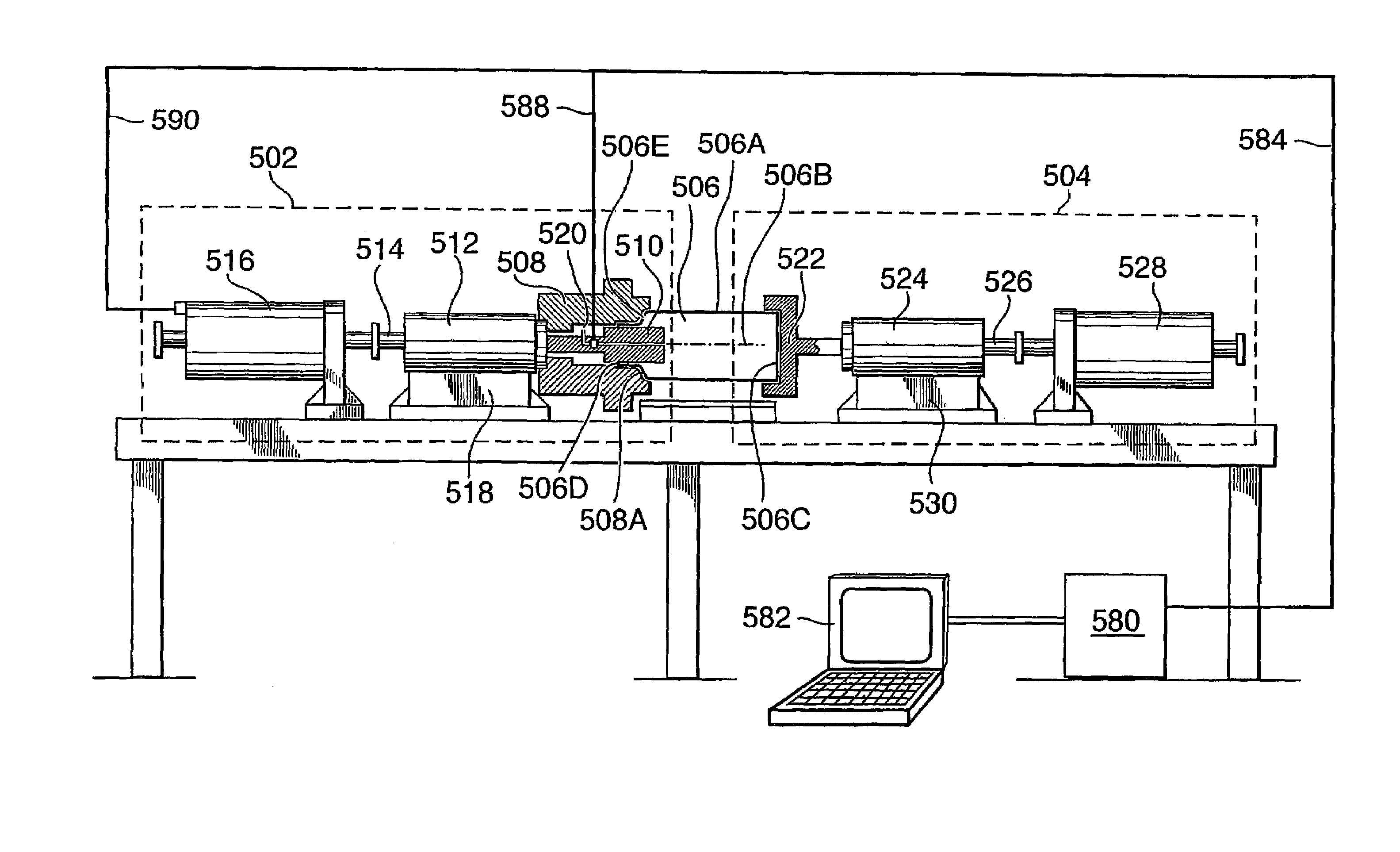
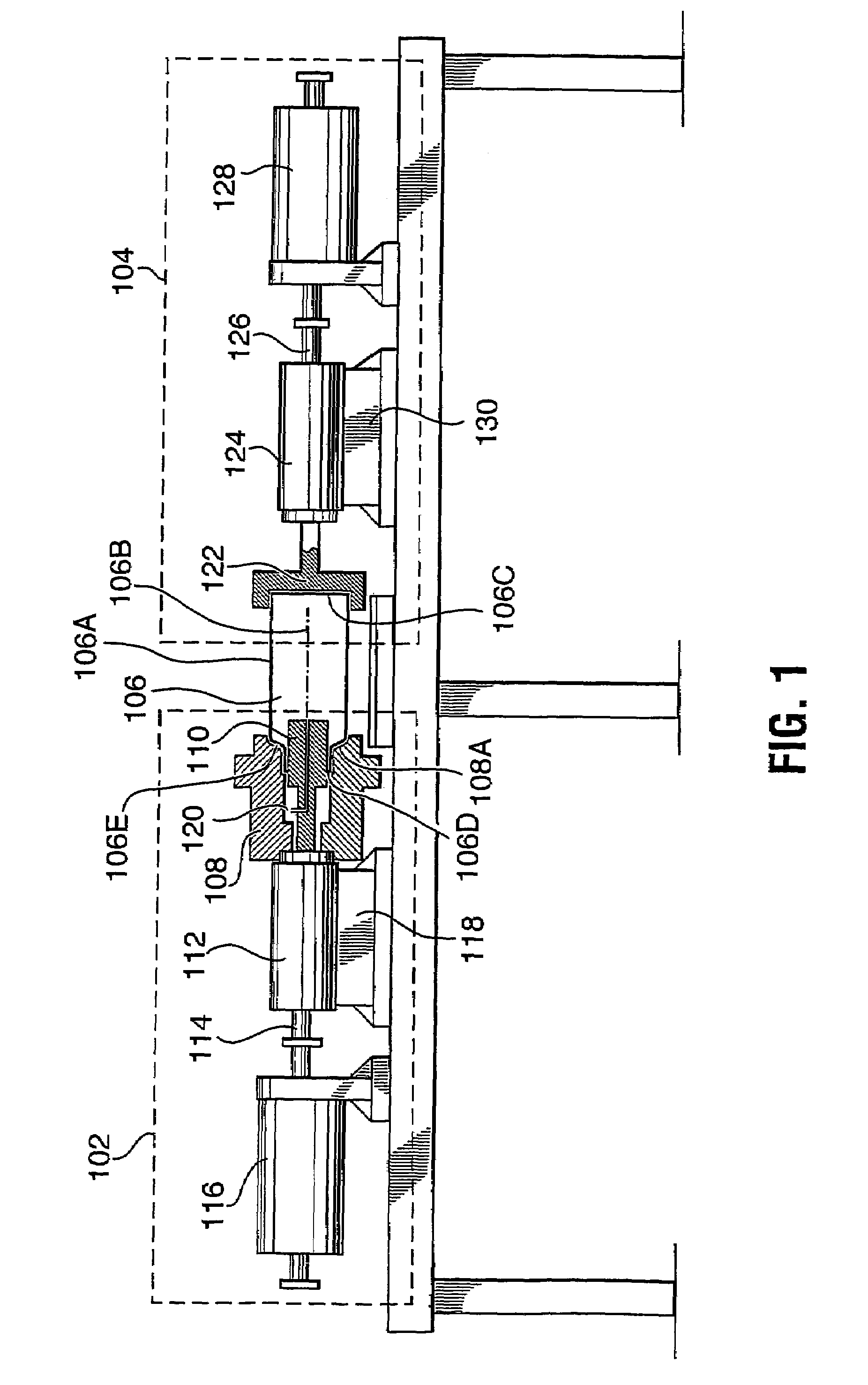
[0026]FIG. 1 of the drawings discloses a schematic illustration of one embodiment of the overall system and apparatus of the present invention. As shown in FIG. 1, the apparatus can be viewed as including a forming segment 102 and a drive segment 104 (illustrated within dotted lines) that together carry out operations on a seamless unitary metal container body 106 to achieve a reduction in the diameter of the sidewall 106A of the body, an operation also known as die necking. Die necking is initiated by the stroke of a first linear motor 116, which is preferably a linear drive motor, acting as a prime mover. The first linear motor 116 generates an inwardly directed longitudinal force on a knockout ram 114 that is transmitted to a knockout element 110 (often referred to simply as a “knockout”). The knockout ram 114 is secured by a knockout ram bushing / die retainer 112 which allows the knockout ram to experience linear motion in the direction of the longitudinal axis 106B of the metal ...


PUM

PropertyMeasurementUnit
diameteraaaaaaaaaa
forceaaaaaaaaaa
pressureaaaaaaaaaa

Abstract

The invention relates to a method and apparatus for forming metal containers. The method involves introducing a knockout element (110) into the container body through the open end, providing a forming die shaped to reduce the diameter of the sidewall of the container body (100) when the open end of the container body (106) is forced therein to produce a neck portion of reduced diameter on the container body, driving the open end of the container body into the forming die (108), retracting the knockout element through the neck portion as the neck portion is formed, and removing the container body (106) from the forming die (108) and knockout element (110). In the invention, the driving of the open end of the container body into the forming die and / or the movements of the knockout element are carried out under computer numerical control, preferably employing linear motor drives, thereby enabling the driving or movement to be optimized for the container body and the neck portion formed thereon.

Description

[0001]The entire disclosure of U.S. Provisional Patent Application No. 60 / 385,865, filed Jun. 3, 2002, is expressly incorporated by reference herein.TECHNICAL FIELD[0002]The present invention generally pertains to the method and apparatus for producing containers and, more particularly, to die necking of such containers.BACKGROUND ART[0003]The technology for reducing the open-end portion of a closed end container (necking) has been in existence for over one hundred years. The procedure was originally developed for artillery shells, with a larger diameter shell casing being reduced to retain a smaller diameter projectile. The process by which this is accomplished today is called die necking. The basic concept of necking is to force a typically cylindrical, thin walled metal body or shell at a given diameter and physically push it into a die or series of progressively smaller dies. In this process a reduction in diameter of the open end is realized.[0004]In metal food and beverage can...

Claims


Application Information

Patent Timeline
Patent Type & Authority Patents(United States)
IPC IPC(8): B21D41/04B21D51/26
CPCB21D51/2615B21D41/04B21D51/26
Inventor GEHO, JEFFREY EDWARDCOOK, JR., HAROLDOLSON, CHRISTOPHER J.ATKINSON, MICHAEL L.KENNEDY, WILLIAM
Owner CROWN PACKAGING TECH
Why Eureka
Try Eureka