
Method for designing a tire with reduced cavity noise

a technology of cavity noise and design method, which is applied in vehicle tyre testing, ways, instruments, etc., can solve the problems of increasing undesirable noise generated by the resonance frequency of the air contained in the tire cavity, and the difficulty of car manufacturers, so as to improve noise performance and reduce acoustic energy

Inactive Publication Date: 2006-07-11
MICHELIN RECH & TECH SA
View PDF33 Cites 9 Cited by
  • Summary
  • Abstract
  • Description
  • Claims
  • Application Information

AI Technical Summary

Benefits of technology

[0008]It is thus an object of the invention to provide a method for designing pneumatic tires having improved noise performance, and, in particular, reduced acoustic energy due to the first cavity mode frequency.
[0009]It is another object of the invention to provide a tire having improved noise performance, and in particular reduced acoustic energy due to the first cavity mode.BRIEF SUMMARY OF THE INVENTION
[0011]Rather than incorporating a separate sound attenuating device in the tire or wheel, the solution in accordance with the invention modifies the tire architecture to avoid the generation of unwanted sound. A sound attenuating device is therefore no longer required.
[0015]Tests show that if a tire is designed so that the tire mode frequency is relatively near the cavity mode frequency, the vibration is substantially reduced or, better, suppressed compared to the conventionally designed tire.
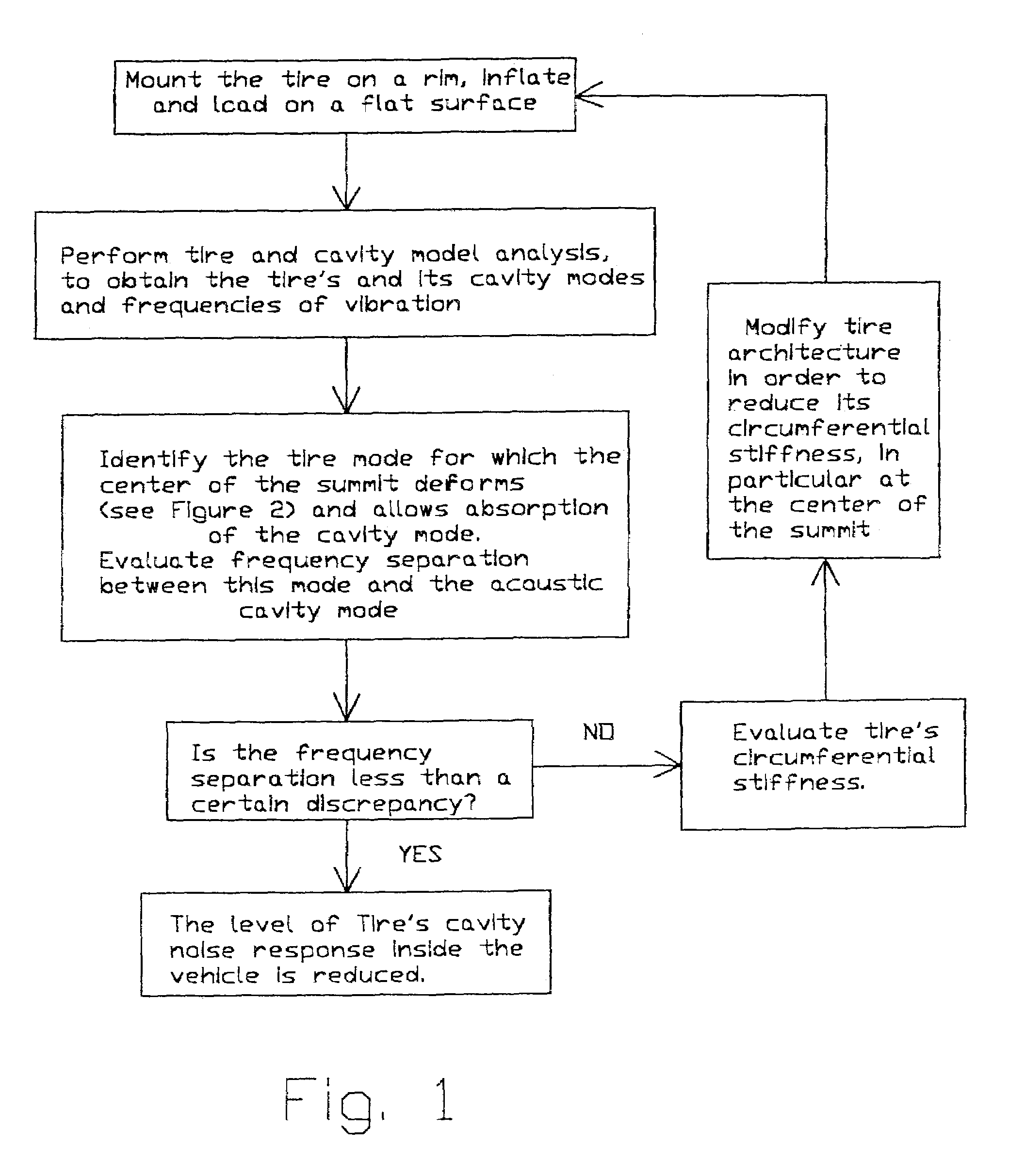
[0020]The invention also provides a method for designing tires, said tires having architectural elements comprising at least one carcass structure anchored in each side of the tire in a bead, each bead having a base which is intended to be mounted on the tire's design mounting rim, a side wall portion extending radially upward from each bead, a reinforced summit comprising reinforcement layers provided with reinforcement cords disposed at a given angle, the side wall portions joining said summit, wherein the tire architectural elements are adapted to optimize said tire's circumferential stiffness in order to obtain a frequency difference between the tire mode and the cavity mode minimized or at least lower than a given value.

Problems solved by technology

Cavity mode noise regularly causes difficulties to car manufacturers.
As cars are to be more and more quiet, the noise generated by the resonance frequency of the air contained in the tire cavity becomes increasingly undesirable.
However, they all require an additional element inside the tire / wheel assembly, or modifications of the wheel / rim assembly.

Method used


Image

  • Method for designing a tire with reduced cavity noise
  • Method for designing a tire with reduced cavity noise
  • Method for designing a tire with reduced cavity noise

Examples


Embodiment Construction

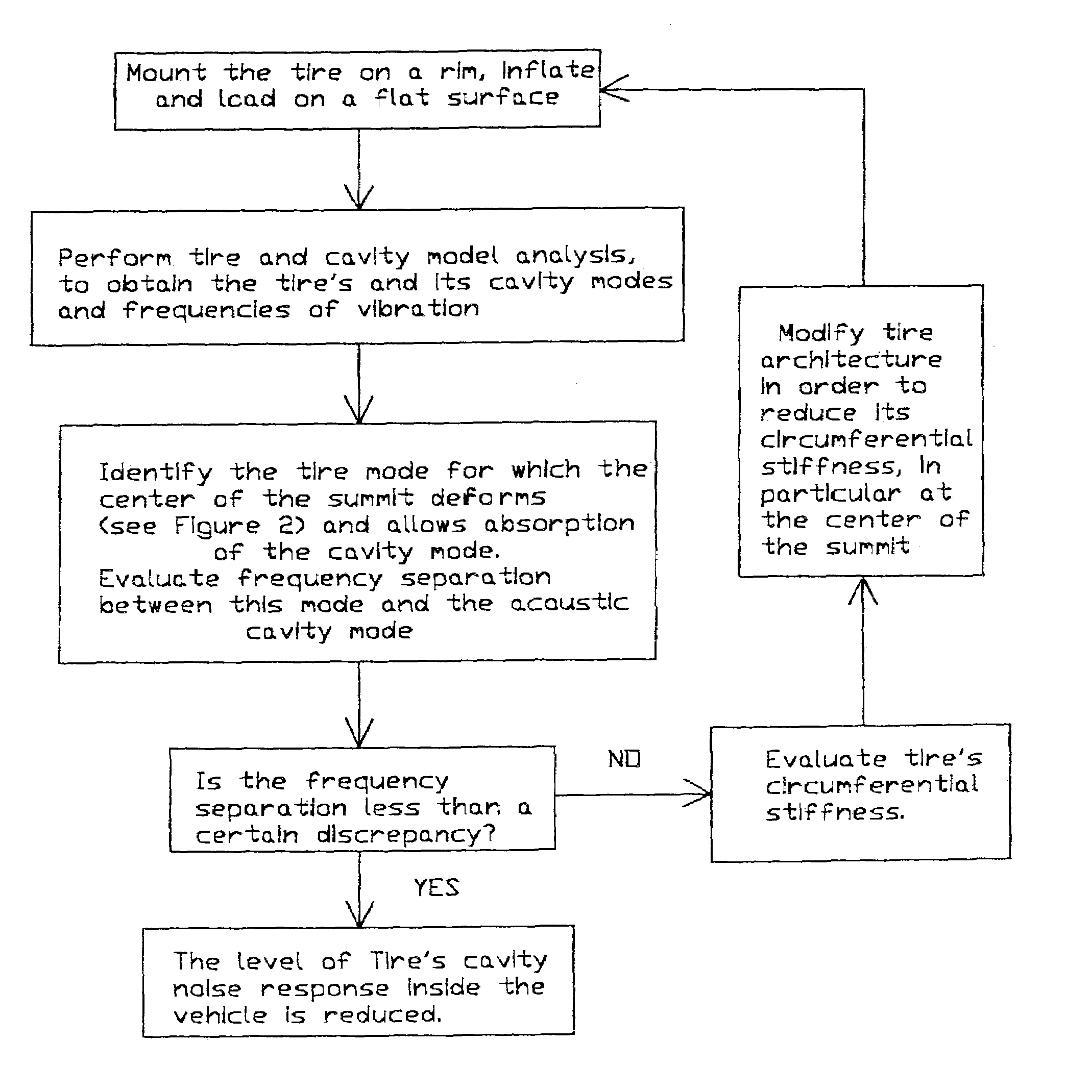
[0030]FIG. 1 is a flow chart illustrating the general methodology of the invention. The method may be carried out using either finite element simulation or experimentally. Different tire designs may be used as a starting point to compare the behavior of each tire with respect to noise due to cavity resonance. Alternatively, the method may be used to design a unique tire having advantageous cavity resonance characteristics.

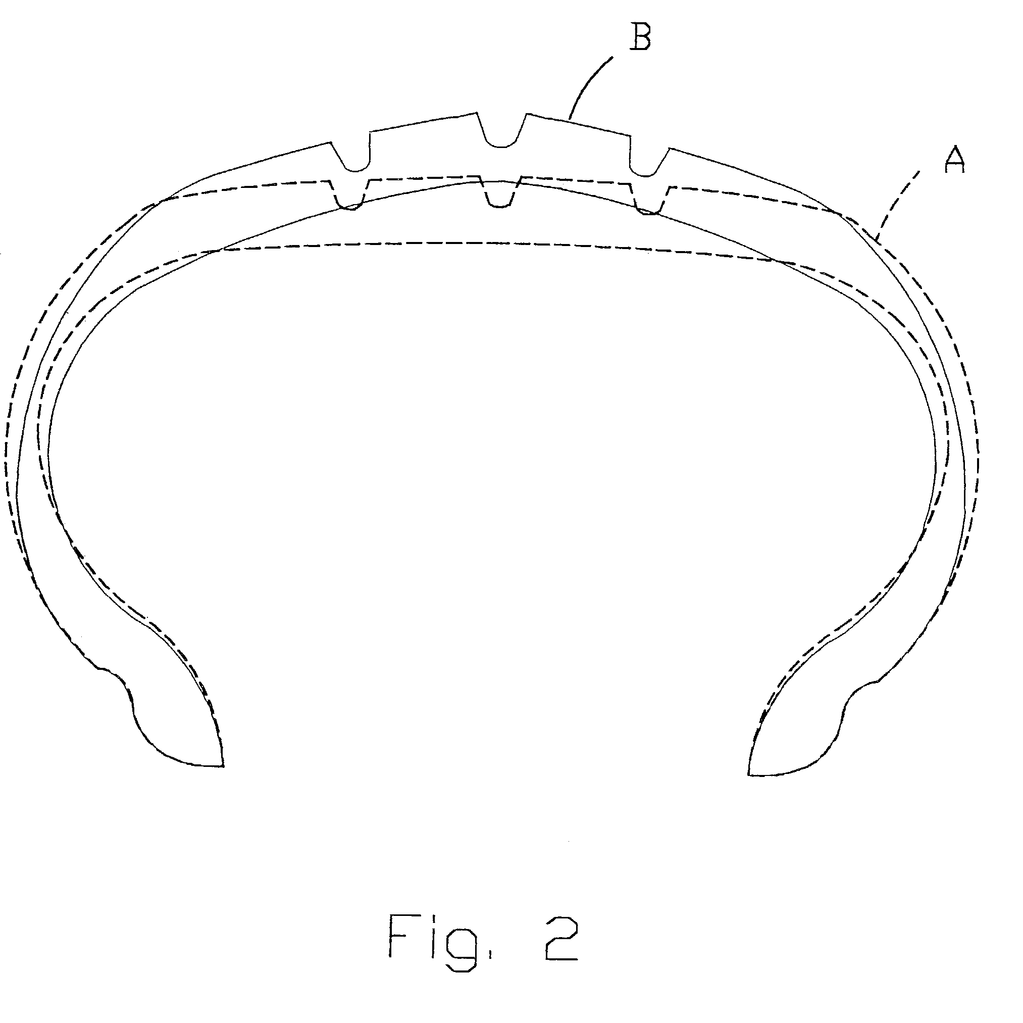
[0031]The inventor discovered that a tire frequency mode at which the summit of the tire deforms can be determined for certain summit architectures, and further, that the noise transmitted from such a tire is related to a difference between the tire frequency mode and the cavity frequency mode. Further, the inventor discovered that the tire frequency mode can be changed by modifying the tire architecture, while the cavity frequency mode is fixed for a given interior volume, thus, allowing a method for controlling noise transmission.

[0032]According to the method of ...


PUM

PropertyMeasurementUnit
angleaaaaaaaaaa
angleaaaaaaaaaa
angleaaaaaaaaaa

Abstract

A method for designing tires for reduced cavity noise is directed to tires of the type having architectural elements comprising at least one carcass structure anchored in each side of the tire in a bead, each bead having a base which is intended to be mounted on the tire's design mounting rim, a side wall portion extending radially upward from each bead, a reinforced summit comprising reinforcement cords disposed at a given angle, and the side wall portions joining the summit. The method includes the step of arranging the architectural elements to provide a flexibility level of at least a portion of the summit to allow said portion to vibrate at a frequency substantially corresponding to the cavity mode.

Description

[0001]This application is a continuation of international application PCT / US00 / 25645, filed on Sep. 19, 2000.BACKGROUND OF THE INVENTION[0002]The invention relates to a method of designing tires having improved noise characteristics, in particular in relation with the first cavity mode frequency.[0003]Cavity mode noise regularly causes difficulties to car manufacturers. As cars are to be more and more quiet, the noise generated by the resonance frequency of the air contained in the tire cavity becomes increasingly undesirable.[0004]Different types of solutions have been developed by different manufacturers to reduce the cavity noise and / or other type of noise. For example, such solutions may use the following features:[0005]foam material on rim;[0006]Helmholtz or quarter-wave resonators either placed in the wheel or in an insert provided in the wheel cavity.[0007]Most of the known solutions seem to give positive test results. However, they all require an additional element inside th...

Claims


Application Information

Patent Timeline
Patent Type & Authority Patents(United States)
IPC IPC(8): B29D30/06B29D30/70B60C5/00B60C9/18G01M17/02B60C9/20
CPCB60C9/18B60C9/20B60C19/002Y10T152/10792Y10T152/10765Y10T152/10495B60C2009/2025
Inventor TSIHLAS, DIMITRIVINESSE, ERIC
Owner MICHELIN RECH & TECH SA
Learn More