Casing hanger annulus monitoring system

a technology of casing and annulus, which is applied in the direction of sealing/packing, drilling pipes, and well accessories, etc., can solve the problems of affecting the flow path of cement slurry, leaking in one of the casing strings, and affecting the operation of well pressure control

Inactive Publication Date: 2006-07-11
ABB VETCOGRAY
View PDF21 Cites 59 Cited by
  • Summary
  • Abstract
  • Description
  • Claims
  • Application Information

AI Technical Summary

Problems solved by technology

An open fluid communication passage in the casing hanger leading from the casing annulus to the casing interior would adversely affect the flow path of the cement slurry.
This could also cause well pressure control problems for the operator under certain conditions.
If pressure within this annulus increases, it would indicate that a leak exists in one of the strings of casing.
Regardless of where the leak is coming from, pressure build up in the annulus between the production casing and the next larger string of casing could collapse a portion of the production casing, compromising the structural and pressure integrity of the well.
Monitoring production casing annulus pressure in a subsea well is more difficult because of lack of access to the wellhead housing below the production casing hanger packoff.

Method used


Image

  • Casing hanger annulus monitoring system
  • Casing hanger annulus monitoring system
  • Casing hanger annulus monitoring system

Examples


Embodiment Construction

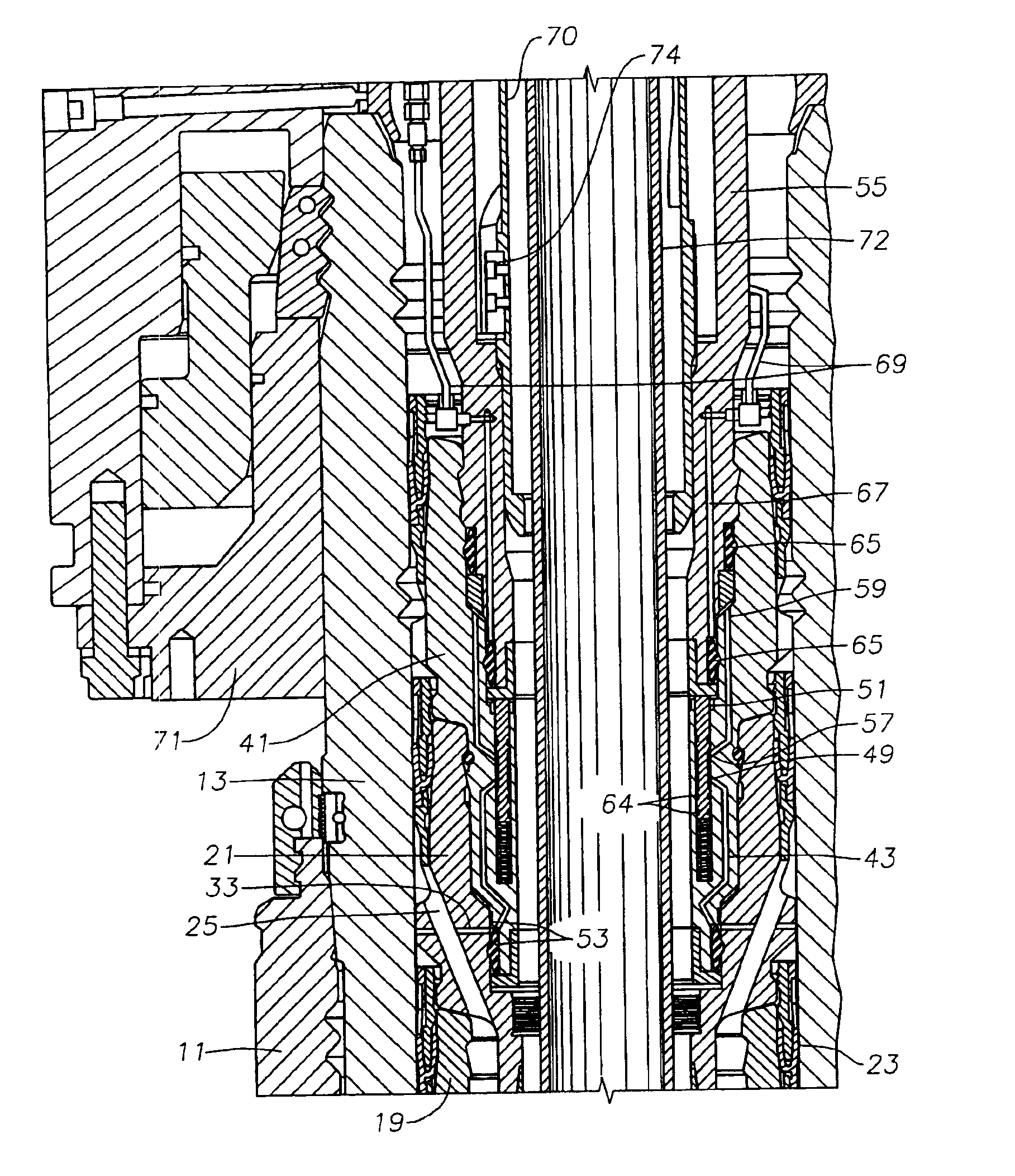
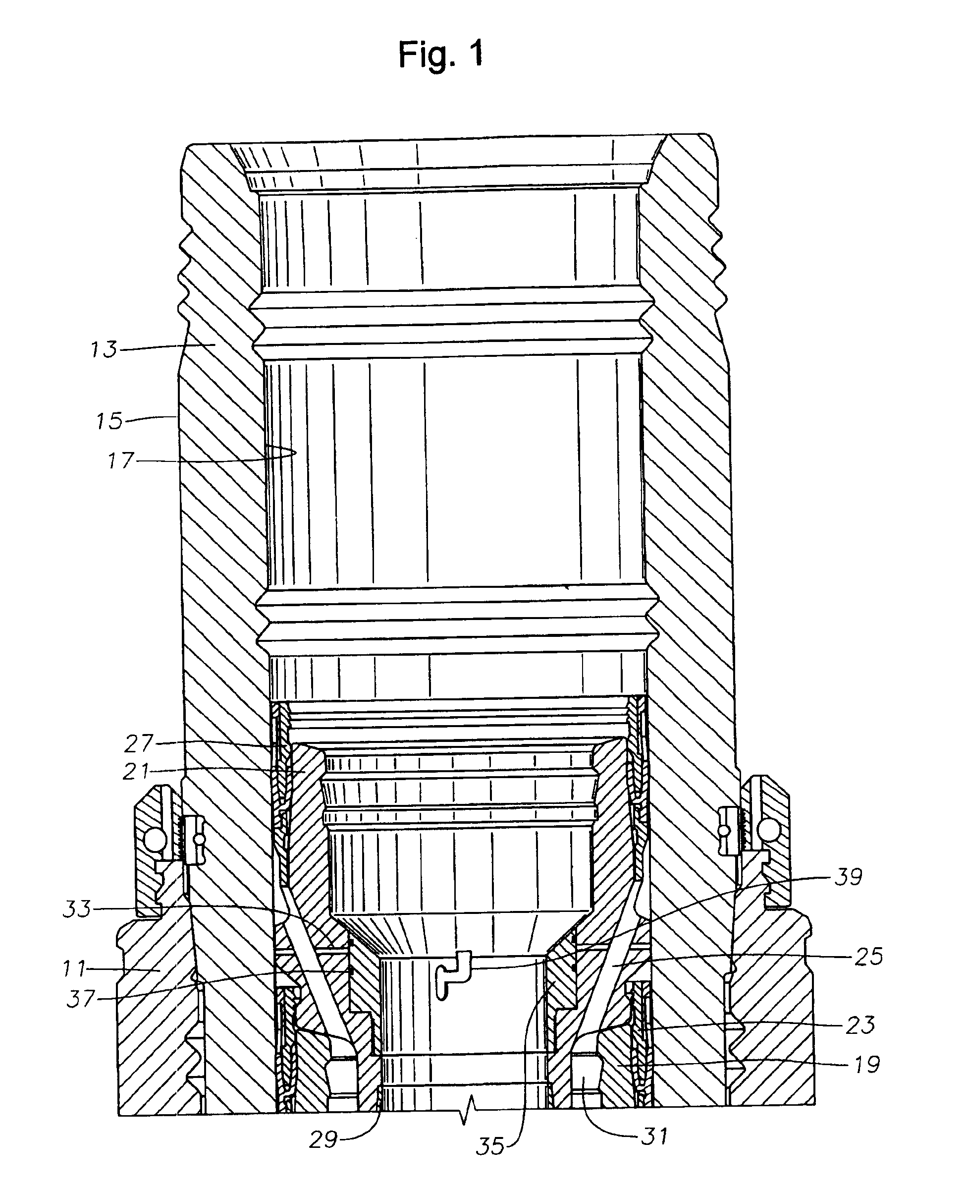
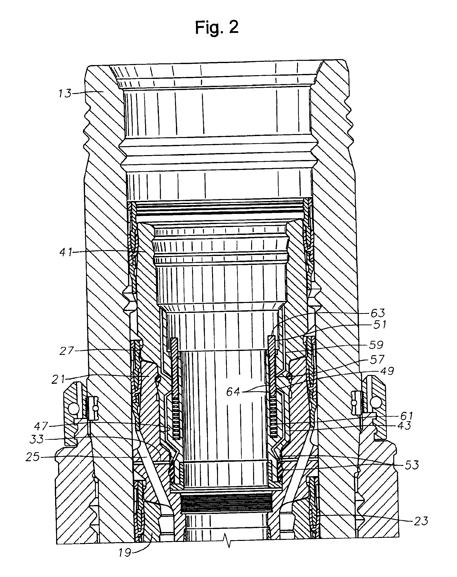
[0023]Referring to FIG. 1, one configuration for the subsea wellhead assembly includes a conductor housing 11, which will locate at the sea floor. Conductor housing 11 is a large tubular member that is secured to a string of conductor pipe (not shown). Conductor pipe (not shown) extends to a first depth into the well. A tubular wellhead member or wellhead housing 13 lands in the conductor housing 11. Wellhead housing 13 is typically a high pressure tubular member having an exterior surface 15 and an interior surface 17. Wellhead housing 13 secures to a first string of casing, which extends through the conductor pipe (not shown) to a deeper depth into the well. Normally, the first string of casing (not shown) is cemented in place.

[0024]Typically, an intermediate casing hanger 19 and intermediate casing (not shown) are installed in wellhead housing 13 in the first string of casing. Intermediate casing hanger 19 lands on a lower shoulder located on interior surface 17 of the wellhead h...


PUM


Abstract

A subsea wellhead assembly has the capabilities of communicating from a tree assembly mounted on an inner wellhead housing to a casing annulus. A passage in the wellhead assembly extends within the bore of the wellhead housing from the casing annulus to the tree assembly. A portion of the passage is located within a casing hanger. The passage is opened and closed by a valve. The valve does not open the passage until the tree assembly is connected to the wellhead housing and a tubing hanger orientation sleeve lands in the wellhead assembly. The tubing hanger orientation sleeve actuates the valve when it lands to open the passage. When the passage is opened, the casing annulus is in fluid communication with the interior surface of the wellhead housing, which is in communication with the tree assembly. The valve can be located in the casing hanger, or in a bridging hanger

Description

RELATED APPLICATIONS[0001]Applicant claims priority to the application described herein through a United States provisional patent application titled “Casing Hanger Annulus Monitoring System,” having U.S. Patent Application Ser. No. 60 / 344,288, which was filed on Dec. 28, 2001, and which is incorporated herein by reference in its entirety.[0002]This application is a continuation of Ser. No. 10 / 330,453, filed Dec. 27, 2002 now abandoned.BACKGROUND OF THE INVENTION[0003]1. Technical Field[0004]This invention relates in general to offshore drilling and production equipment, and in particular to a subsea well system for monitoring the pressure in a non-producing string of casing through the completion system.[0005]2. Description of Related Art[0006]A subsea well that is capable of producing oil or gas will have a conductor housing secured to a string of conductor pipe which extends some short depth into the well. A wellhead housing lands in the conductor housing. The wellhead housing is...

Claims


Application Information

Patent Timeline
Patent Type & Authority Patents(United States)
IPC IPC(8): E21B34/04E21B33/043E21B33/035E21B33/076
CPCE21B33/076E21B33/035
Inventor MASSIE, ALFREDMOORE, HARRY A.LOVELL, RICHARDBUCKLE, KEVIN G.OSBORNE, JOHN H.
Owner ABB VETCOGRAY
Why Eureka
Try Eureka