Hydraulic pressure control apparatus for vehicular hydraulic power transmission device with lock-up clutch

a hydraulic power transmission device and hydraulic pressure control technology, which is applied in the direction of rotary clutches, fluid couplings, gearings, etc., can solve the problems of inability to control the flow rate of hydraulic oil when the orifice is opened, increase the frictional heat generated by slippage, and reduce the hydraulic pressure in the engagement side oil chamber. , to achieve the effect of sufficient transmission torque capacity of the lock-up clutch, and increase the hydraulic pressure in the engagement side oil chamber

Active Publication Date: 2006-07-11
TOYOTA JIDOSHA KK
View PDF13 Cites 6 Cited by
  • Summary
  • Abstract
  • Description
  • Claims
  • Application Information

AI Technical Summary

Benefits of technology

[0010]With this configuration, the switching control valve switches between connection and disconnection between each of the second oil passage and the third oil passage that communicate with the engagement side oil chamber, and each of the high pressure oil passage from which the high pressure hydraulic oil is introduced and the low pressure oil passage to which the low pressure hydraulic oil is discharged, according to the operating state of the lock-up clutch (i.e., a disengagement state, a slip state, and a complete engagement state). Therefore, the operating state of the lock-up clutch (i.e., the disengagement state, the slip state, and the complete engagement state) is appropriately controlled using the hydraulic pressure difference between the engagement side oil chamber and the disengagement side oil chamber. When the lock-up clutch is completely engaged, the switching control valve allows both the second oil passage and the third oil passage to be connected to the high pressure oil passage such that the hydraulic oil is supplied to both the second oil passage and the third oil passage that communicate with the engagement side oil chamber from the high pressure oil passage, and the hydraulic pressure in the engagement side oil chamber is increased. When the lock-up clutch is disengaged, the switching control valve allows both the second oil passage and the third oil passage to be connected to the low pressure oil passage such that the hydraulic oil is discharged to the low pressure oil passage from both the second oil passage and the third oil passage that communicate with the engagement side oil chamber, and the hydraulic pressure in the engagement side oil chamber is decreased. Thus, the operating state of the lock-up clutch is appropriately controlled. Particularly, when the lock-up clutch is completely engaged, a sufficient transmission torque capacity of the lock-up clutch is obtained. Further, when the lock-up clutch is in the slip state, the switching control valve allows one of the second oil passage and the third oil passage that communicate with the engagement side oil chamber to be connected to the high pressure oil passage, and allows the other oil passage to be connected to the low pressure passage such that the hydraulic oil is circulated. Therefore, an increase in the temperature of the hydraulic oil is suppressed, a slip surface of the lock-up clutch is cooled when the lock-up clutch is in the slip state, and thus the durability of the frictional material is improved.
[0011]Also, the switching control valve may allow the second oil passage and the third oil passage to be connected to the low pressure oil passage when the lock-up clutch is disengaged. With this configuration, the hydraulic pressure in the engagement side oil chamber can be promptly decreased, and therefore the control operation can be appropriately performed when the lock-up clutch is disengaged.
[0012]Also, the switching control valve may allow the second oil passage and the third oil passage to be connected to the high pressure oil passage when the lock-up clutch is completely engaged. With this configuration, the hydraulic oil does not flow from the engagement side oil chamber when the lock-up clutch is completely engaged, and cooling by circulation of the hydraulic oil is not necessary since heat is not generated by the slip. Therefore, a decrease in the hydraulic pressure in the engagement side oil chamber can be prevented, the control operation can be appropriately performed when the lock-up clutch is completely engaged, and a sufficient torque capacity of the lock-up clutch is obtained.
[0014]With this configuration, the switching control valve switches between connection and disconnection between each of the second oil passage and the third oil passage that communicate with the engagement side oil chamber, and each of the high pressure oil passage from which the high pressure hydraulic oil is introduced and the low pressure oil passage to which the low pressure hydraulic oil is discharged, according to the operating state of the lock-up clutch. Therefore, the operating state of the lock-up clutch is appropriately controlled using the hydraulic pressure difference between the engagement side oil chamber and the disengagement side oil chamber. When the lock-up clutch is completely engaged, the switching control valve allows both the second oil passage and the third oil passage to be connected to the high pressure oil passage such that the hydraulic oil is supplied to both the second oil passage and the third oil passage that communicate with the engagement side oil chamber from the high pressure oil passage, and the hydraulic pressure in the engagement side oil chamber is increased. When the lock-up clutch is disengaged, the switching control valve allows both the second oil passage and the third oil passage to be connected to the low pressure oil passage such that the hydraulic oil is discharged to the low pressure oil passage from both the second oil passage and the third oil passage that communicate with the engagement side oil chamber, and the hydraulic pressure in the engagement side oil chamber is decreased. Thus, the operating state of the lock-up clutch is appropriately controlled. Particularly, when the lock-up clutch is completely engaged, a sufficient transmission torque capacity of the lock-up clutch is obtained. Further, when the lock-up clutch is in the slip state, the switching control valve allows one of the second oil passage and the third oil passage that communicate with the engagement side oil chamber to be connected to the high pressure oil passage, and allow the other oil passage to be connected to the low pressure passage such that the hydraulic oil is circulated. Therefore, an increase in the temperature of the hydraulic oil is suppressed, a slip surface of the lock-up clutch is cooled when the lock-up clutch is in the slip state, and thus the durability of the frictional material is improved. Further, the pressure adjusting valve controls the hydraulic pressure in the low pressure oil passage, independently of the switching control valve, and the circulation flow amount of the hydraulic oil in the engagement side oil chamber is appropriately set. Therefore, the lock-up clutch is cooled more appropriately, the durability of the frictional material is improved, and the slip control is performed more appropriately.

Problems solved by technology

When the lock-up clutch is frequently placed in the slip state, frictional heat that is generated due to the slip increases.
The durability of the frictional material may deteriorate due to heat deterioration caused by the frictional heat.
However, in the case of the aforementioned bimetal orifice, only opening / closing thereof can be controlled, and a flow rate of the hydraulic oil when the orifice is opened cannot be controlled.
Thus, the control operation for the lock-up clutch, for example, the slip control operation may not be appropriately performed.

Method used


Image

  • Hydraulic pressure control apparatus for vehicular hydraulic power transmission device with lock-up clutch
  • Hydraulic pressure control apparatus for vehicular hydraulic power transmission device with lock-up clutch
  • Hydraulic pressure control apparatus for vehicular hydraulic power transmission device with lock-up clutch

Examples


Embodiment Construction

[0024]Hereinafter, an embodiment of the invention will be described with reference to drawings.

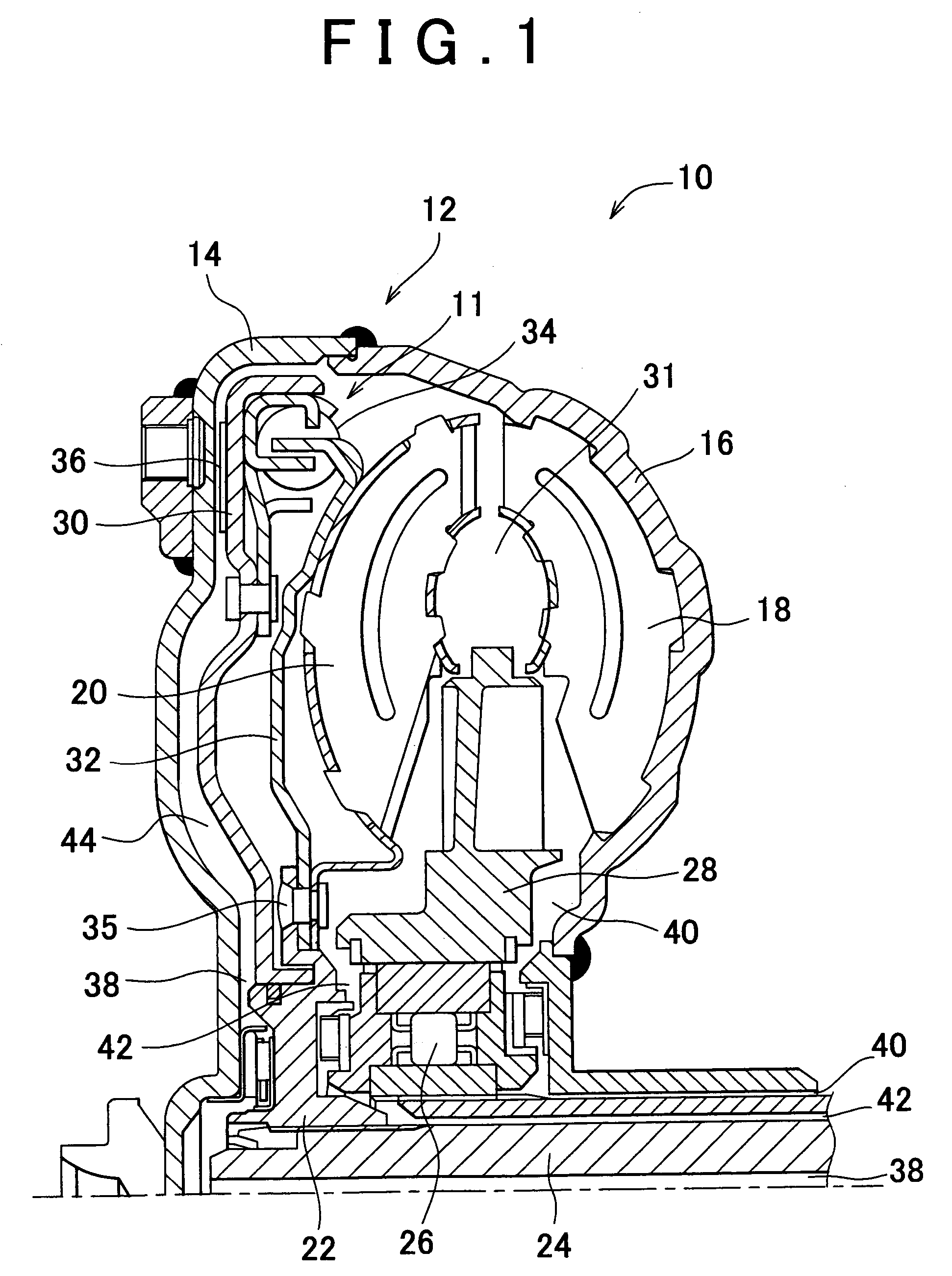
[0025]FIG. 1 is a diagram showing a torque converter 10 including a lock-up clutch 11 which is a hydraulic transmission device according to an embodiment of the invention. The torque converter 10 includes a cover 12 which is an input side rotational member, and which is rotated integrally with a crank shaft of an engine (not shown). The cover 12 includes a front cover 14 that is a cover on the engine side (on the left side in FIG. 1), and a pump shell 16 that is a cover on a transmission side (on the right side in FIG. 1). The front cover 14 and the pump shell 16 are integrally coupled by welding. The front cover 14 and the pump shell 16 are configured so as to be oil-tight. The front cover 14 has a cylinder shape having a bottom, and is opened in one way. The outer peripheral portion of the pump shell 16 is coupled to the outer peripheral portion of the opening portion of the front cover ...


PUM


Abstract

There is provided a hydraulic pressure control apparatus for a vehicular hydraulic power transmission device with a lock-up clutch, in which an increase in the temperature of hydraulic oil in an engagement side oil chamber is suppressed, durability of frictional material is improved, and the lock-up clutch is appropriately controlled.A switching control valve (a lock-up relay valve 250 and a lock-up control valve 252) switches between connection and disconnection between each of two oil passages that communicate with an engagement side oil chamber 31, and each of a high pressure oil passage and a low pressure oil passage, according to the operating state of the lock-up clutch 11. For example, when the lock-up clutch is completely engaged, the hydraulic oil is supplied to both the two oil passages from the high pressure oil passage, hydraulic pressure PON in the engagement side oil chamber 31 is increased, and a sufficient transmission torque capacity of the lock-up clutch 11 is obtained. When the lock-up clutch 11 is in the slip state, one of the two oil passages is connected to the high pressure oil passage, and the other oil passage is connected to the low pressure oil passage such that the hydraulic oil is circulated in the engagement side oil chamber 31. Therefore, an increase in the temperature of the hydraulic oil is suppressed, the lock-up clutch 11 is cooled, and the durability of the frictional material 36 is improved.

Description

INCORPORATION BY REFERENCE[0001]The disclosure of Japanese Patent Application No. 2003-139552 filed on May 16, 2003 including the specification, drawings and abstract is incorporated herein by reference in its entirety.BACKGROUND OF THE INVENTION[0002]1. Field of the Invention[0003]The invention relates to a hydraulic pressure control apparatus for a vehicular hydraulic power transmission device which includes a lock-up clutch whose operating state can be changed using a hydraulic pressure difference between an engagement side oil chamber and a disengagement side oil chamber.[0004]2. Description of the Related Art[0005]A vehicle is known, which includes a lock-up clutch that can mechanically connect an input side and an output side of a hydraulic power transmission device such as a torque converter and a fluid coupling such that torque can be directly transmitted. The lock-up clutch is disposed between a front cover that is an input side rotational member of the hydraulic power tran...

Claims


Application Information

Patent Timeline
Patent Type & Authority Patents(United States)
IPC IPC(8): F16H61/14
CPCF16H61/143F16H2061/145
Inventor MORISE, MASARUSUGAWARA, AKIOTAKEUCHI, HIROAKIYASUDA, YUJI
Owner TOYOTA JIDOSHA KK
Why Eureka
Try Eureka