Conveyor belt and method of assembly

a technology of conveyor belts and pivot rods, applied in the field of modular conveyor belts, can solve the problems of inability to adjust the angle of the pivot rod, so as to reduce the likelihood of tenting during operation

Active Publication Date: 2006-07-11
ASHWORTH BROS
View PDF50 Cites 57 Cited by
  • Summary
  • Abstract
  • Description
  • Claims
  • Application Information

AI Technical Summary

Benefits of technology

[0011]Another advantage of the present invention is in providing a conveyor belt that reduces the likelihood of tenting during operation.
[0012]Still another advantage of the present invention is in providing a conveyor belt with a mechanism to control the minimum turn radius of the conveyor belt.
[0013]Another aspect of the present invention is in providing a method for assembling conveyor belts.
[0014]In accordance with one embodiment of the present invention, a conveyor belt is provided comprising a plurality of link elements and a plurality of pivot rods. Each link element includes a plurality of intermeshing extensions and at least one edge extension at a peripheral edge thereof. The plurality of intermeshing extensions form receiving compartments adapted to receive intermeshing extensions of an adjacent link element, and include transverse rod openings. The plurality of pivot rods are received in the transverse rod openings of the plurality of intermeshing extensions thereby interconnecting adjacent link elements together. At least one edge extension of the plurality of link elements includes an entry aperture sized to allow insertion of a pivot rod through the at least one edge extension, and a protrusion that extends to block an entry aperture of an adjacent link element to retain a pivot rod that interlinks a pair of link elements other than the link element on which the protrusion is provided.
[0015]In accordance with another embodiment, at least some of the transverse rod openings are slotted openings to allow the plurality of link elements of the conveyor belt to be collapsed together. The edge extension may include a receiving slot defined by an upper flange and a lower flange, the receiving slot being sized to receive a protrusion of an adjacent link element when the link elements are collapsed together.
[0016]In addition, the edge extension may further include a rod receiving compartment for receiving an end of a pivot rod therein. The edge extension may further include a transverse obstruction that at least partially defines the rod receiving compartment. In one implementation, the obstruction may be a continuous divider. In another implementation, the obstruction may be one or more projections. The projections may be curved with a radius that is substantially the same as a radius of the pivot rod.

Problems solved by technology

However, this patent requires the rods to be moved over the ridge via deformation of the ridge which can weaken the links depending on the material from which the links are made.
Moreover, inadvertent removal of the rods can occur if the rod is unintentionally moved to a position in which the pivot rod aligns with the exit-entrance aperture.
The insertion of the pivot rods at an angle is cumbersome and may often be difficult to achieve whereas use of a bendable pivot rod is not desirable in many applications due to reduced strength.
However, providing side rails for the length of the conveyor belt is cost prohibitive.
This patent discloses that the protrusion includes a notch so as to allow the pivot rod to be inserted into the apertures of the hinge elements but does not prevent unintentional removal of the rod.
However, the conveyor belts do not provide an integrated solution to these issues associated with use of conveyor belts.
Therefore, there still exists an unfulfilled need for a conveyor belt that provides an integrated solution to such issues.
In particular, there still exists an unfulfilled need for a conveyor belt that allows easy installation and retention of pivot rods.
In addition, there still exists an unfulfilled need for a conveyor belt that reduces the likelihood of tenting, and provides a mechanism to control the minimum turn radius of a conveyor belt.

Method used


Image

  • Conveyor belt and method of assembly
  • Conveyor belt and method of assembly
  • Conveyor belt and method of assembly

Examples


Embodiment Construction

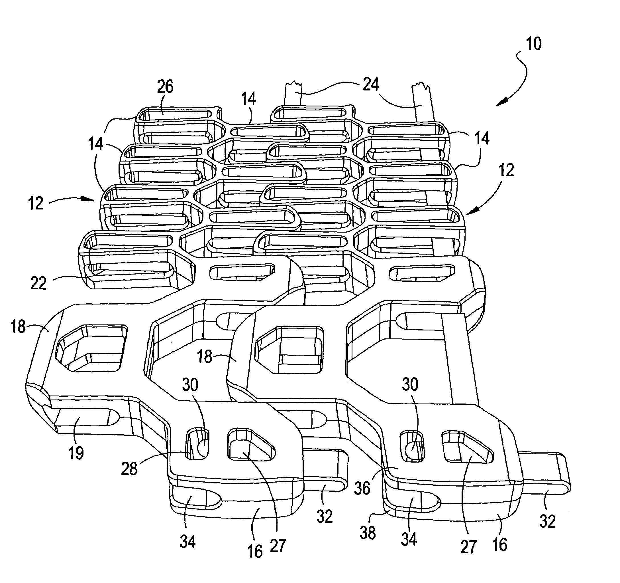
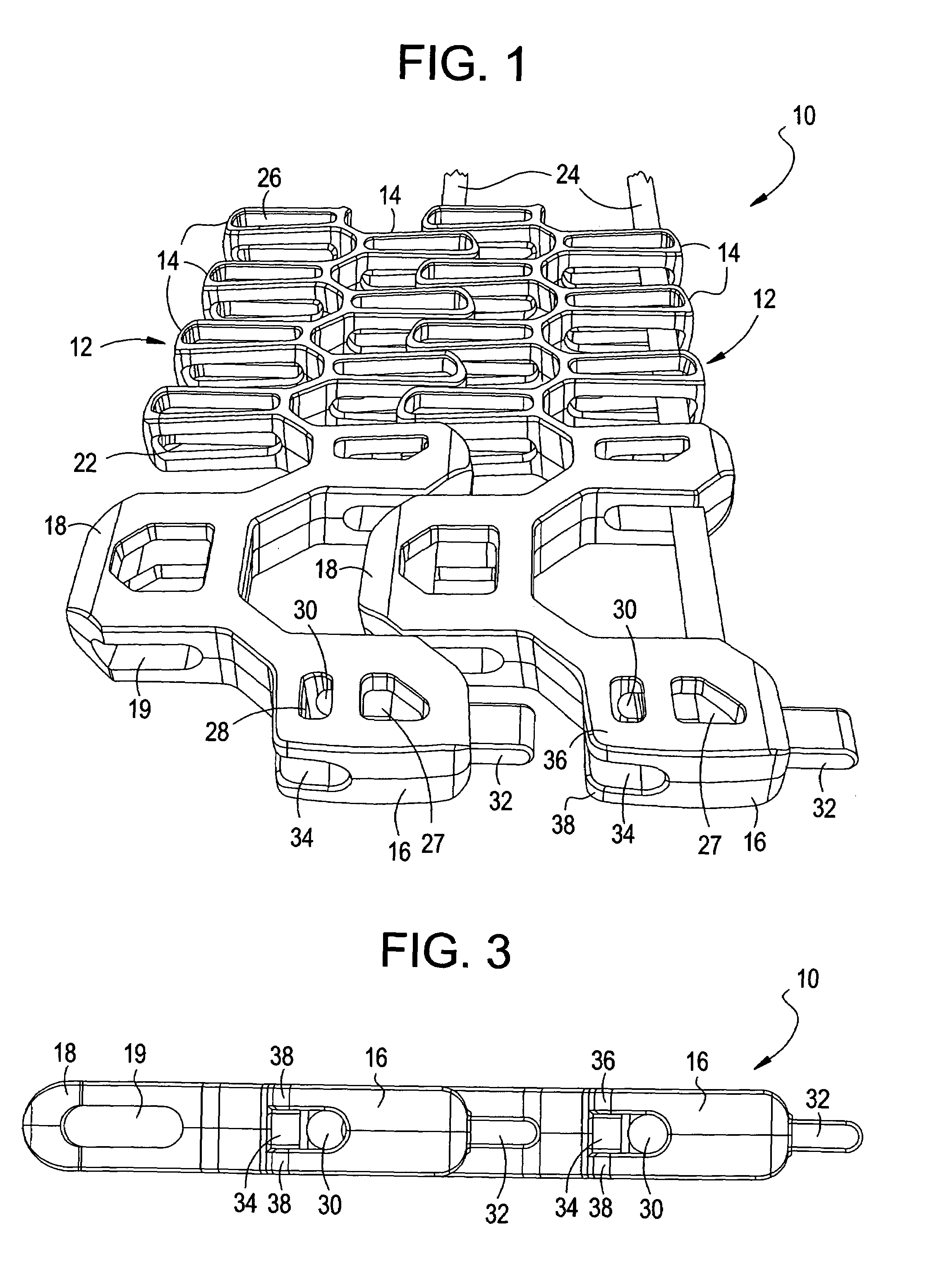
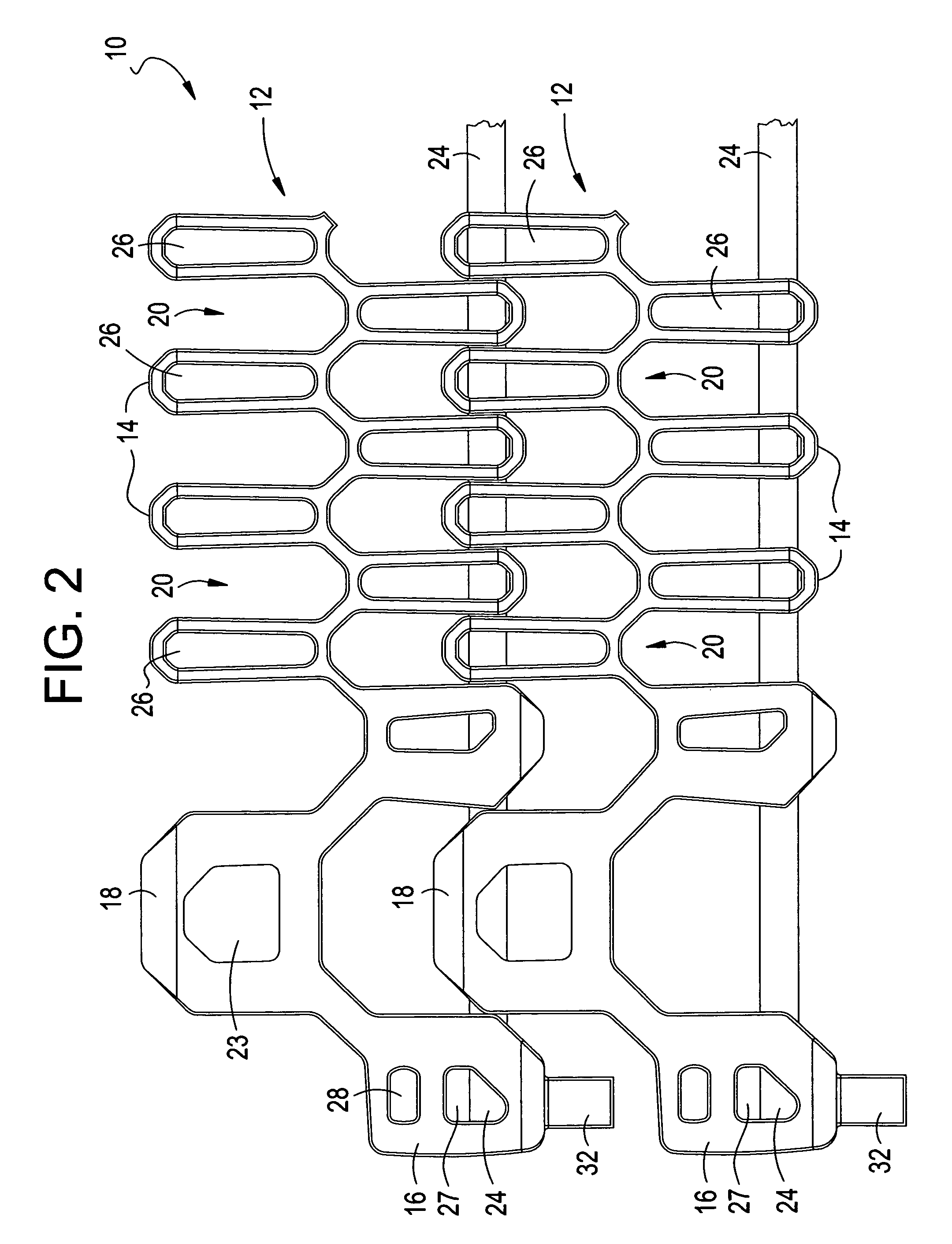
[0040]FIGS. 1 to 7 show various views of a segment of a conveyor belt 10 in accordance with one example embodiment of the present invention which provides an integrated solution to various issues noted previously that is associated with using conveyor belts. As will be described in detail herein below, the conveyor belt 10 allows for easy installation and retention of pivot rods which are used to interconnect a plurality of link elements as described. In addition, conveyor belt 10 as illustrated reduces the likelihood of tenting, and further provides a mechanism for controlling the minimum turn radius of the conveyor belt 10. Various aspects of the present invention, and the advantages thereof, are described herein below in reference to the various figures, especially with respect to FIGS. 1 to 7. However, it should be understood that these figures merely show particular embodiments of the present invention, and that the present invention is not limited to the specific embodiments s...


PUM


Abstract

A conveyor belt and method for assembling a conveyor belt, the conveyor belt including a plurality of link elements and a plurality of pivot rods. Each link element includes a plurality of intermeshing extensions and at least one edge extension at a peripheral edge thereof. The plurality of intermeshing extensions form receiving compartments adapted to receive intermeshing extensions of an adjacent link element, and include transverse rod openings. The plurality of pivot rods are received in the transverse rod openings of the plurality of intermeshing extensions thereby interlinking adjacent link elements together. The edge extensions include an entry aperture sized to allow insertion of a pivot rod, and a rod receiving compartment to retain an end of the pivot rod.

Description

BACKGROUND OF THE INVENTION[0001]1. Field of the Invention[0002]The present invention is directed to conveyor belts, and in particular, to modular conveyor belts. The present invention is further directed to methods for assembling such belts.[0003]2. Description of Related Art[0004]Conveyor systems are commonly used in various industrial fields for material handling and processing purposes. For instance, conveyor systems are used in food processing systems in which food items are placed on the support surface of a conveyor belt and are processed while being conveyed from one location to another. In such applications, the food items may be cooked, baked, frozen, washed, or subject to other processing steps while being conveyed on the conveyor belt. Various different types of conveyor belts have been used in such applications such as wire mesh conveyor belts but various modular belts have become especially popular in food processing systems. Moreover, such conveyor systems are often u...

Claims


Application Information

Patent Timeline
Patent Type & Authority Patents(United States)
IPC IPC(8): B65G17/06B65G17/08
CPCB65G17/06B65G17/086B65G2207/12B65G2207/30
Inventor NEELY, D. JOSEPHLASECKI, JONATHAN R.VAN FAASSEN, WILLEM
Owner ASHWORTH BROS
Why Eureka
Try Eureka