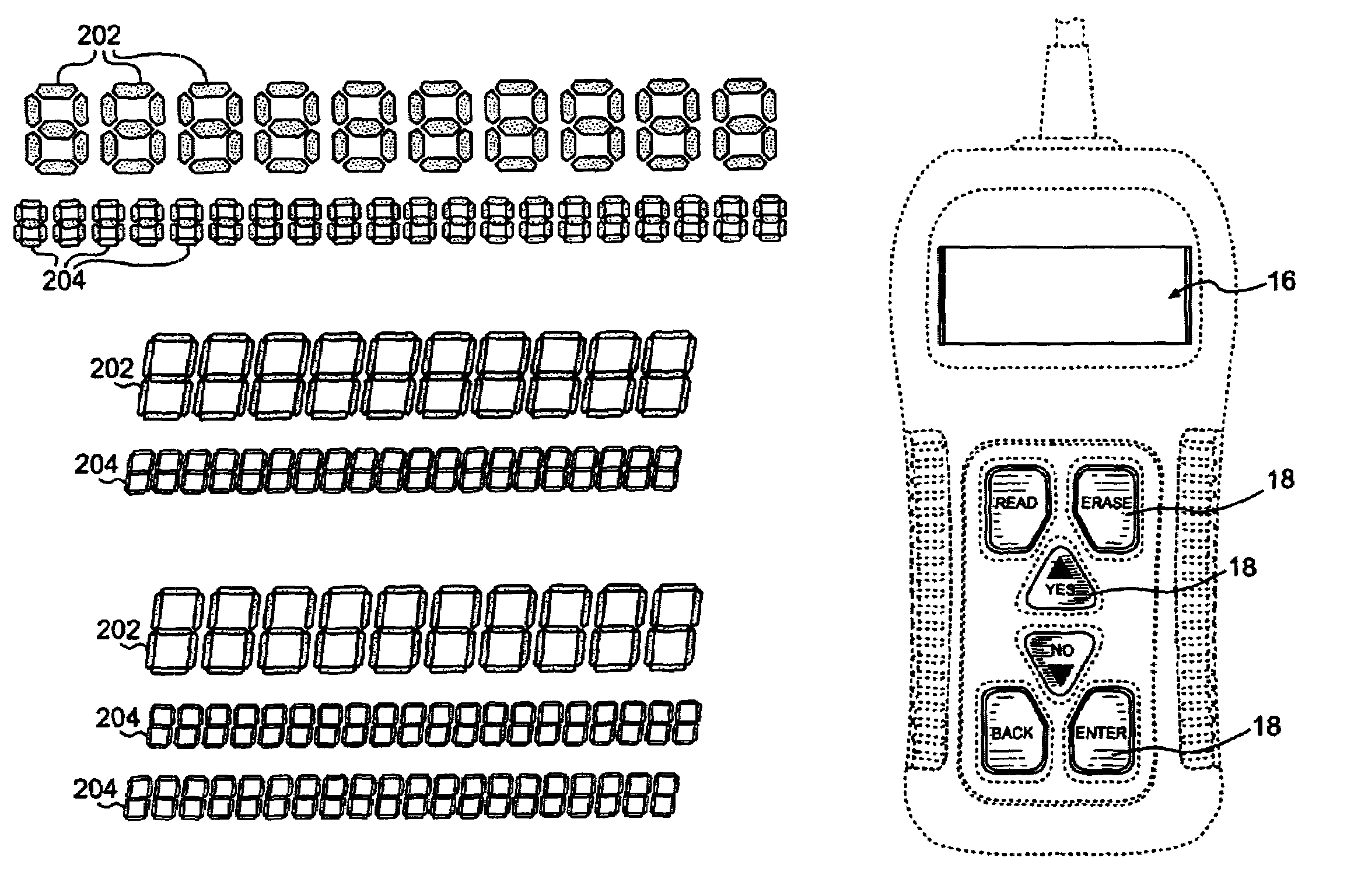
Code reader display

a code reader and display technology, applied in the field of electronic testing devices, can solve the problems of human error, manual reading of obd ii and/or manufacturer-specific textual diagnosis descriptions, and relatively expensive scan tools

Active Publication Date: 2006-07-11
SPX CORP
View PDF41 Cites 47 Cited by
  • Summary
  • Abstract
  • Description
  • Claims
  • Application Information

AI Technical Summary

Benefits of technology

[0018]It is therefore an advantage of the present invention to provide an improved code reader that displays a several character diagnostic code on a larger display along with a textual diagnosis description corresponding to the diagnostic code on a smaller display.
[0019]It is another advantage of the present invention to provide an improved code reader that has a display that has at least two rows of display characters available for displaying information, with one row having display characters that are significantly larger than (and preferably about twice as large as) the other row(s).
[0020]It is still another advantage of the present invention to provide an improved code reader that has either (a) a 1-by-

Problems solved by technology

Scan tools are relatively expensive diagnostic devices that have a relatively large number of features and are typically marketed to professional automobile mechanics and service stations.
As used here, an “OBD II Scan Tool” is significantly different from a manufacturer-specific “scan tool.” A given off-board device might be a scan tool but not an OBD II Scan Tool, because it does not meet applicable specifications.
This process of manually reading the OBD II and/or manufacturer-specific textual diagnosis descriptions can be time-consuming and, of

Method used


Image

  • Code reader display
  • Code reader display
  • Code reader display

Examples


Embodiment Construction

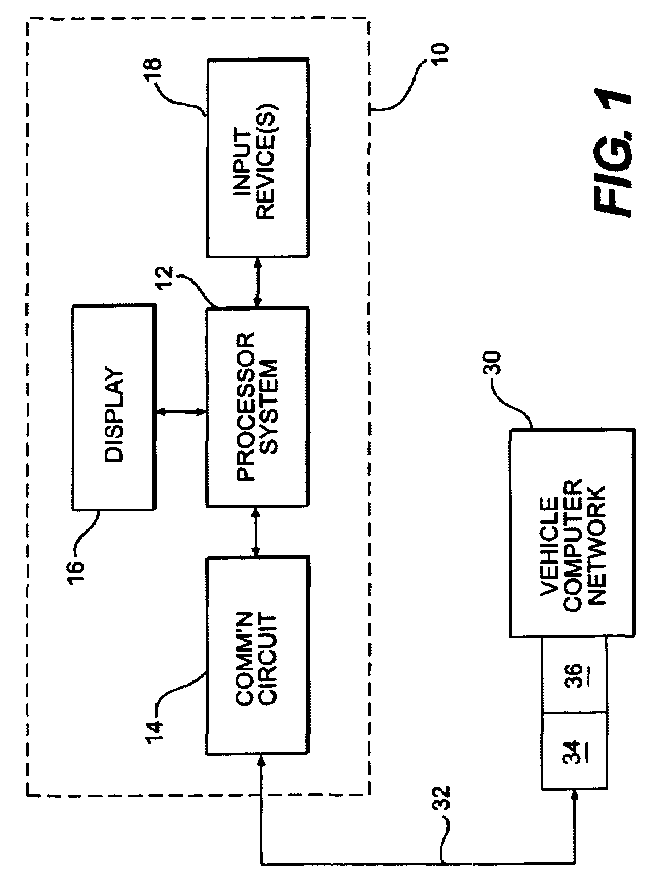
[0038]FIG. 1 illustrates a high-level block diagram of both a typical code reader and a code reader 10 of the present invention. Such a code reader 10 includes a processor system 12 in circuit communication with a communication circuit 14, a display 16, and one or more input devices 18.

[0039]“Circuit communication” as used herein indicates a communicative relationship between devices. Direct electrical, electromagnetic, and optical connections and indirect electrical, electromagnetic, and optical connections are examples of circuit communication. Two devices are in circuit communication if a signal from one is received by the other, regardless of whether the signal is modified by some other device. For example, two devices separated by one or more of the following—amplifiers, filters, transformers, optoisolators, digital or analog buffers, analog integrators, other electronic circuitry, fiber optic transceivers, or even satellites—are in circuit communication if a signal from one is...


PUM


Abstract

An improved code reader for reading and displaying OBD II diagnostic codes. The code reader displays textual diagnosis descriptions corresponding to diagnostic codes. The code reader can display both an OBD II code and the textual diagnosis description corresponding to a selected OBD II code by using multiple display rows for the display. The improved code reader also uses an improved user interface.

Description

CROSS REFERENCE TO RELATED APPLICATION[0001]This application claims the benefit under 35 U.S.C. § 119(e) of U.S. Provisional Application 60 / 371,786, filed Apr. 11, 2002, titled IMPROVED CODE READER DISPLAY, which application is hereby incorporated by reference in its entirety.FIELD OF THE INVENTION[0002]The present invention relates generally to the field of electronic testing devices, and more specifically to a code reader having an improved display and an improved user interface.BACKGROUND OF THE INVENTION[0003]Modern vehicles typically have a vehicle diagnostic system, generally having one or more separate computer control modules. Examples of such computer control modules (also known as just “modules”) are: a powertrain control module (PCM), an engine control module (ECM), a transmission control module (TCM), an ABS control module, and an air bag control module.[0004]“Off-board devices,” such as scan tools, are known in the art and are testing devices that interface with vehicle...

Claims


Application Information

Patent Timeline
IPC IPC(8): G06K7/10G06K7/00G07C5/00G07C5/08
CPCG07C5/0816G07C5/008G09G2340/145
Inventor NAMAKY, HAMIDROBERTS, ROBERT A.KORAN, MATTHEW H.
Owner SPX CORP
Why Eureka
Try Eureka