Stackable chair with flexing frame

a stackable chair and frame technology, applied in the field of stackable chairs, can solve the problems of user little or no range, difficulty in providing comfort in a stackable chair,

Inactive Publication Date: 2006-07-11
HNI TECH INC
View PDF16 Cites 37 Cited by
  • Summary
  • Abstract
  • Description
  • Claims
  • Application Information

AI Technical Summary

Benefits of technology

[0016]It is yet another object of the invention to provide such a flexible stacking chair that is of relatively lightweight construction.

Problems solved by technology

It can be difficult to provide for comfort in a stackable chair, because such chairs are typically constructed of rigid materials fastened together in fixed relation, such that the chair affords the user little or no range of motion.

Method used


Image

  • Stackable chair with flexing frame
  • Stackable chair with flexing frame
  • Stackable chair with flexing frame

Examples


Embodiment Construction

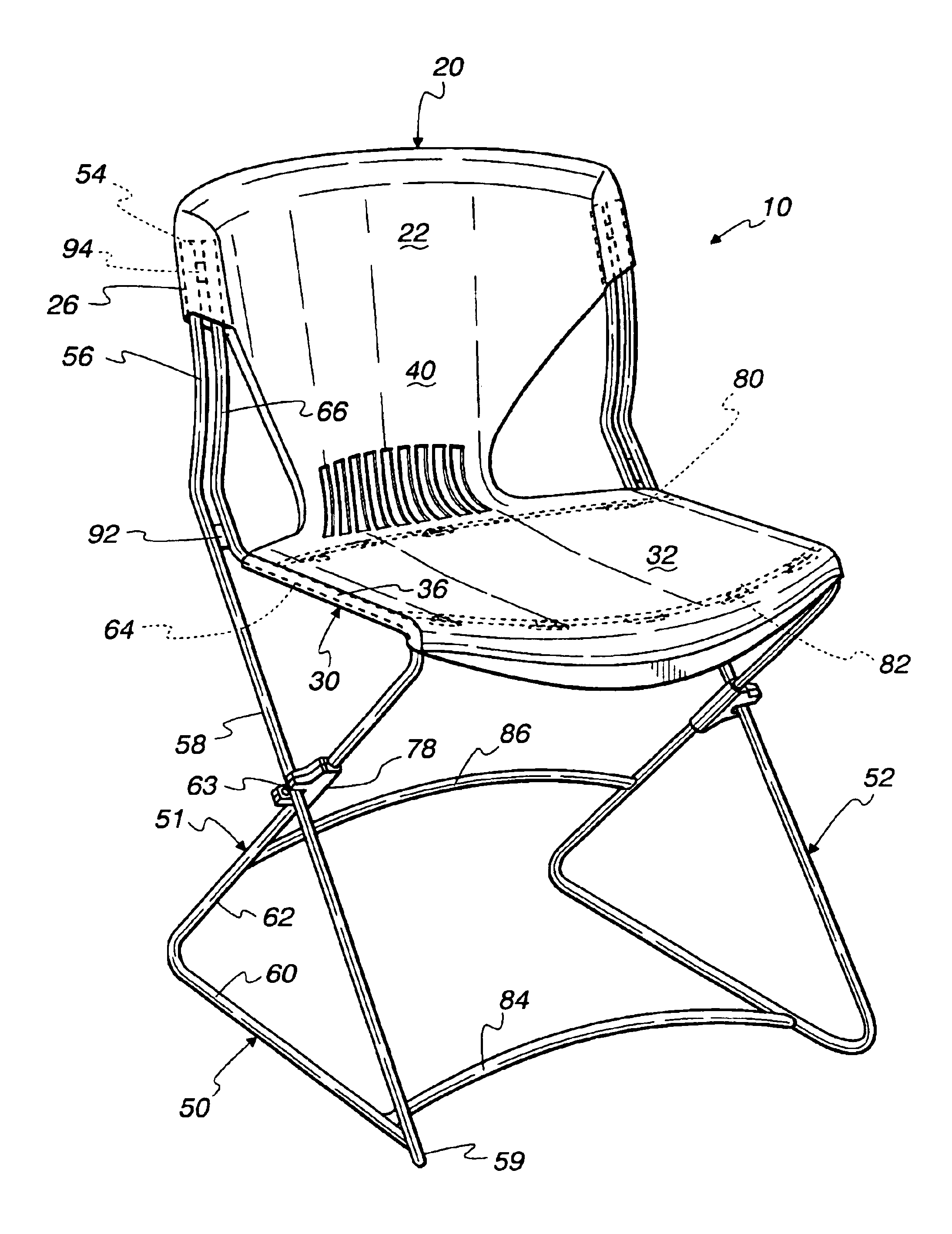
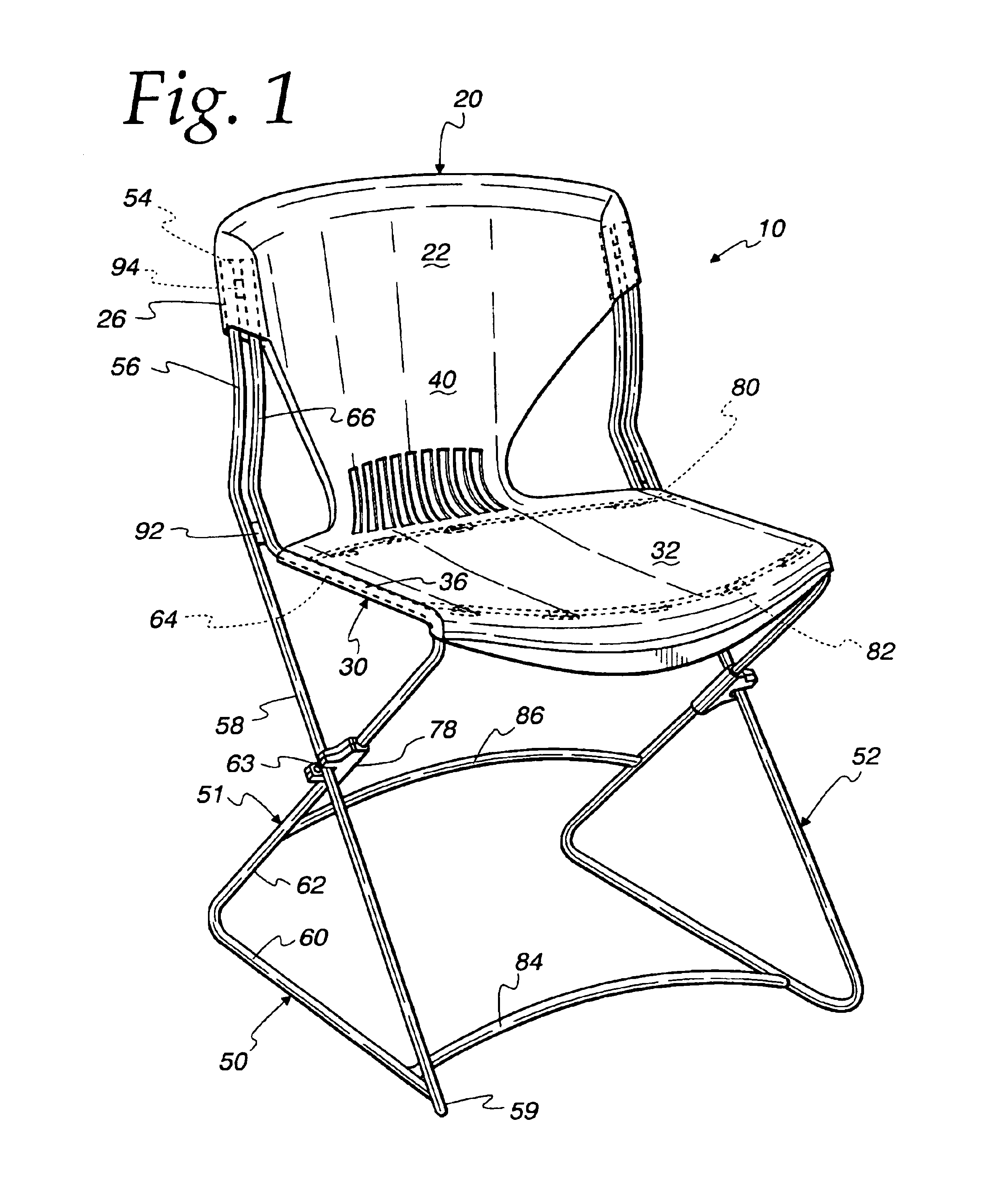
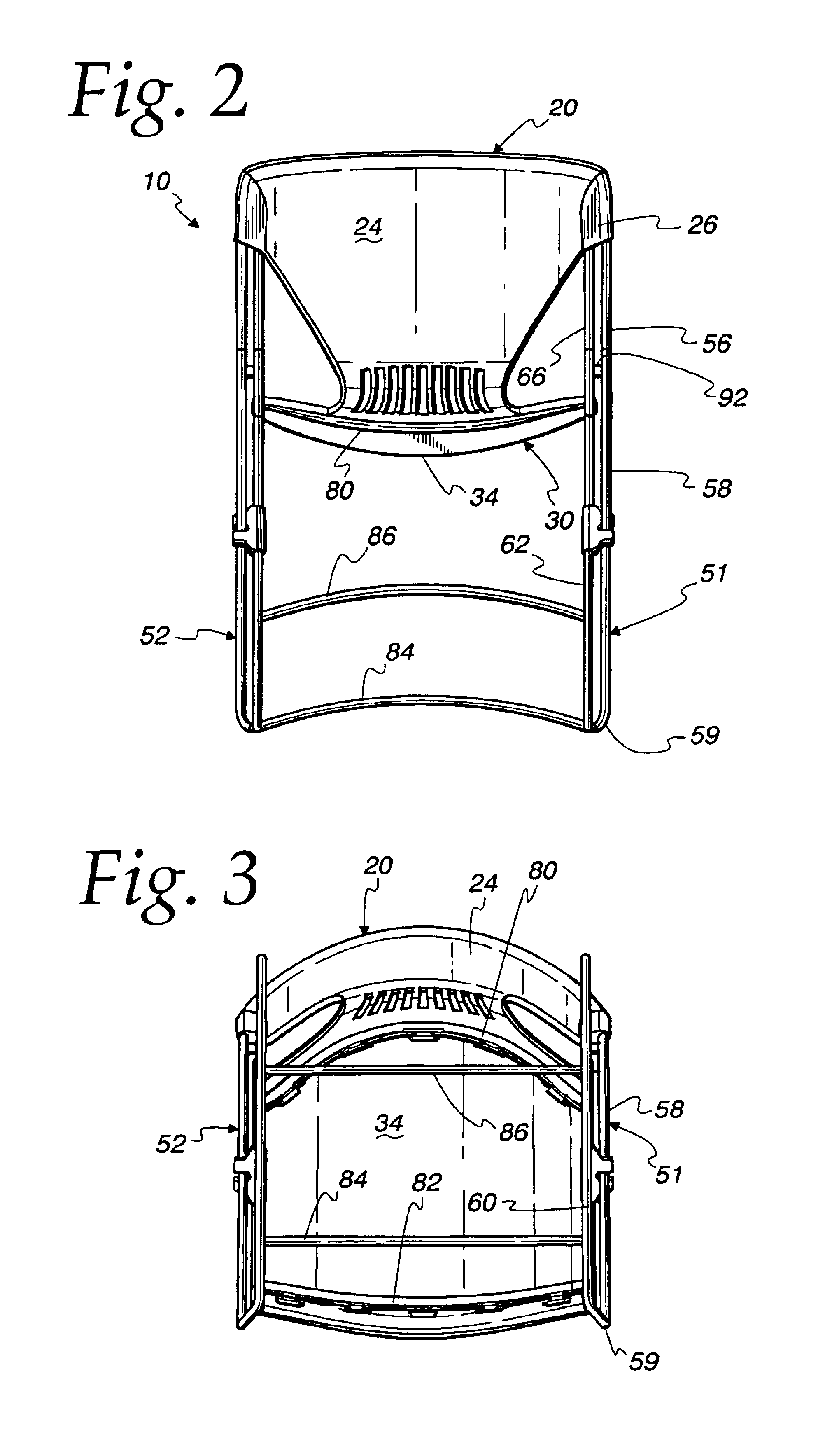
[0029]Turning to FIGS. 1-4, there is illustrated a first embodiment of a chair 10 of the instant invention comprising a frame 50, a back rest member 20, and a seat member 30. In the illustrated embodiment, back rest member 20 and seat member 30 are integrally formed in a unitary shell member 40. Back rest member 20 comprises a front surface 22 and a rear surface 24. Seat member 30 comprises an upper surface 32 and a lower surface 34.

[0030]Frame 50 is made of a material that provides strength, support, and an acceptable range of flexibility. A material that is too stiff will not provide enough flexing action to optimize comfort for the user, while a material that is too flexible will not provide adequate support for some users. Steel wire of 7 / 16″ diameter is a preferred material known to provide sufficient support and flexibility; those skilled in the art may recognize other materials that will also be suitable.

[0031]Frame 50 comprises first and second side members 51 and 52 that ar...


PUM


Abstract

A stackable chair has supporting side members that comprise two bars that cross one another in non-contacting relation to form a substantially X-shaped configuration, the two bars capable of flexing movement relative to one another, so that the chair can flex in response to the weight and movement of the user.

Description

CROSS REFERENCE TO RELATED APPLICATIONS[0001]This application is related to design applications filed on the same date herewith, and having Ser. Nos. 29 / 183,640, 29 / 183,639, 29 / 183,638, 29 / 183,637, and 29 / 183,580.BACKGROUND OF THE INVENTION[0002]This invention relates to stacking chairs, and in particular to stacking chairs having flexing frames to enhance comfort for the user.[0003]Stackable chairs are well known in the art. Such chairs are used to provide temporary seating for large numbers of persons, such as for meetings, conferences and the like. It is desirable that stacking chairs be relatively lightweight and easy to store. It is further desirable that such chairs provide optimum comfort for the user. It can be difficult to provide for comfort in a stackable chair, because such chairs are typically constructed of rigid materials fastened together in fixed relation, such that the chair affords the user little or no range of motion.[0004]U.S. Pat. No. 70,756 discloses a chair ...

Claims


Application Information

Patent Timeline
Patent Type & Authority Patents(United States)
IPC IPC(8): A47C3/04
CPCA47C3/04A47C3/023
Inventor OLSEN, OGDEN R.
Owner HNI TECH INC
Why Eureka
Try Eureka