Direct drive linear flow blood pump

a direct drive, linear technology, applied in the direction of pump, positive displacement liquid engine, liquid fuel engine, etc., can solve the problems of inefficiency of the device, inability to tailor the device to the needs of particular patients or particular circumstances, and blood has substantial viscosity, so as to reduce the unbalanced magnetic force

Inactive Publication Date: 2006-07-11
CHANG SHELDON
View PDF21 Cites 100 Cited by
  • Summary
  • Abstract
  • Description
  • Claims
  • Application Information

AI Technical Summary

Benefits of technology

[0011]Also in the preferred embodiment, the pump stator is connected to the motor rotor for rotation therewith and the motor further includes a motor stator for rotating the motor rotor. The motor stator has at least one pair of windings that are arranged on opposite sides of the motor stator and are connected in parallel to reduce unbalanced magnetic forces. The motor stator is contained between an inner pump housing wall and an outer pump housing wall. Additionally, the motor stator and the motor rotor preferably include longitudinally spaced segments and the motor rotor further preferably includes an outer sleeve for supporting the motor rotor segments. In this preferred embodiment, the drive element is connected to the outer sleeve.

Problems solved by technology

There are several problems with such devices.
Thus, it is difficult to tailor such devices for the needs of particular patients or particular circumstances.
Second, the devices are inefficient, because the initial tendency of the pusher plate is to push the blood in all directions.
However, blood has substantial viscosity and tends to also move radially with the propelling blades or fins.
As the centrifugally moving blood impinges against the walls of the cylindrical conduit, there is not only a loss of energy but also damage to the blood cells.

Method used


Image

  • Direct drive linear flow blood pump
  • Direct drive linear flow blood pump
  • Direct drive linear flow blood pump

Examples


Embodiment Construction

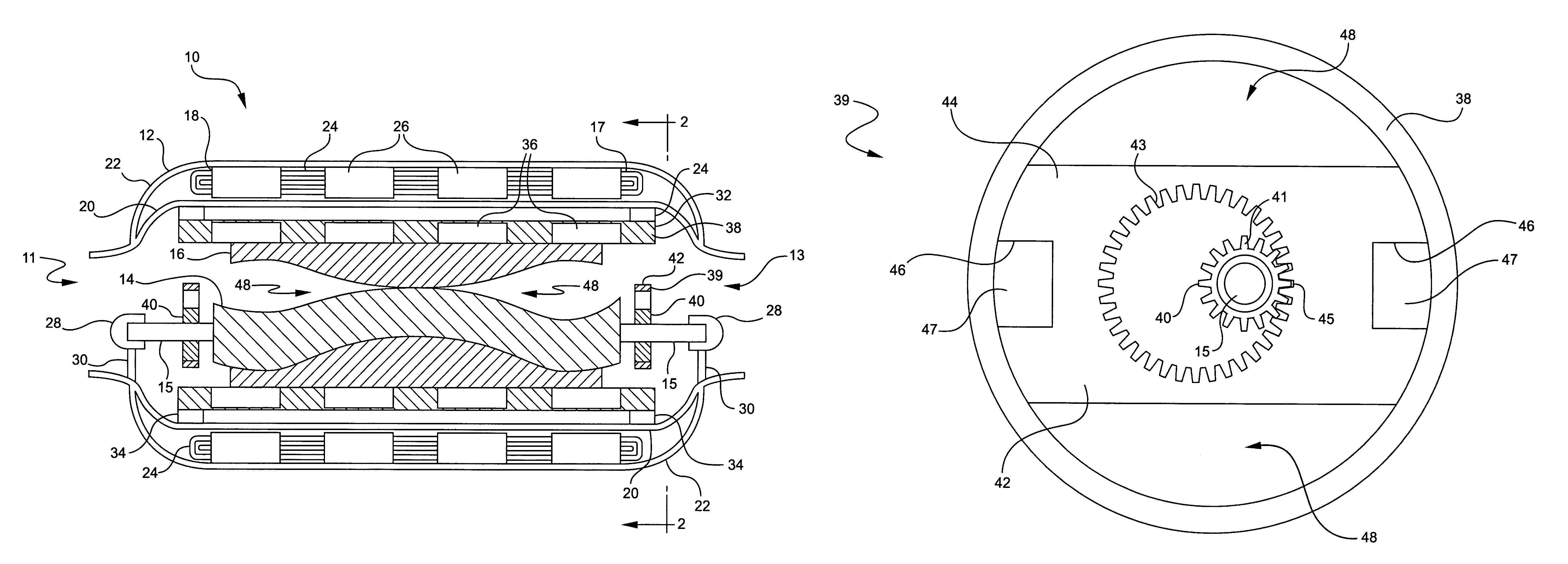
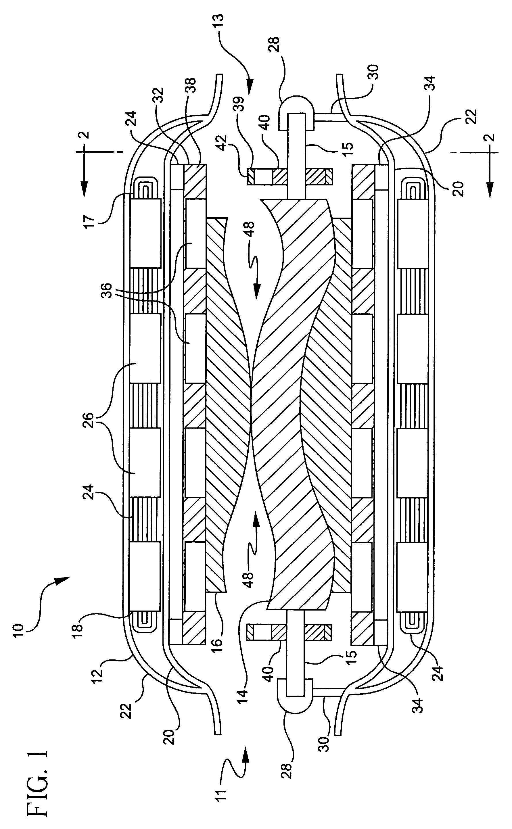
[0017]The invention herein is a ventricular assistive device based on a progressive cavity pump. A progressive cavity pump does not use blades or fins to propel the blood. Instead, the pump stator and rotor are designed so that, when combined, there is a progressive series of cavities formed between the pump rotor and the pump stator. Blood is carried through the pump chamber in these cavities when both the rotor and the stator rotate.

[0018]Referring to FIG. 1, the pump 10 of the present invention generally includes a pump housing 12 defining an inlet 11 and an outlet 13 and having contained therein a pump rotor 14 and a pump stator 16. The pump rotor 14 is helical in shape, somewhat like a single-threaded screw, and preferably has a circular cross-section. The pump stator 16 resembles a double-threaded screw, closely engaged with the pump rotor 14.

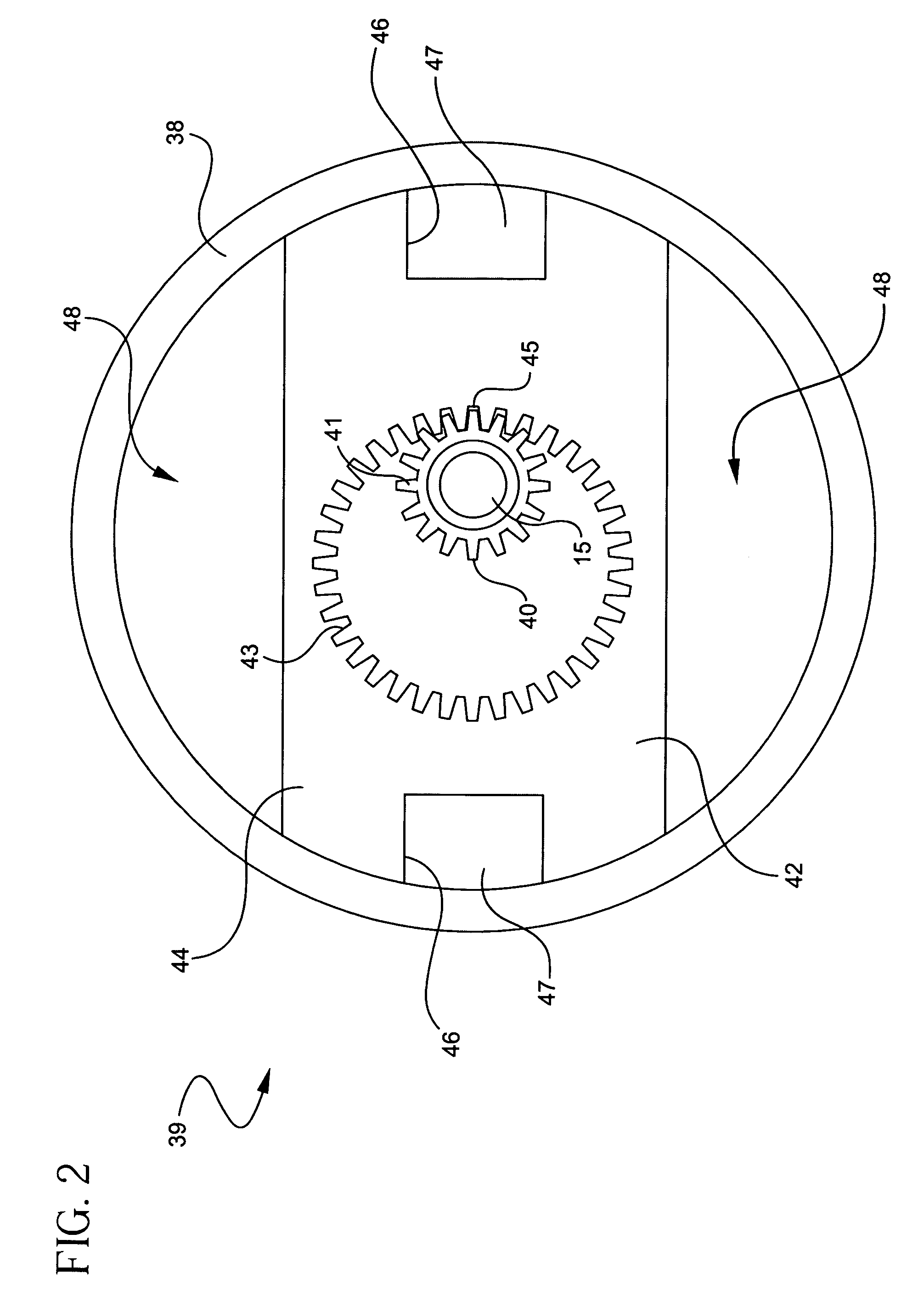
[0019]In a preferred embodiment, a gear arrangement 39 drives the pump rotor 14 to rotate with the pump stator 16 in the same direction....


PUM


Abstract

A ventricular assistive device (VAD) based on a progressive cavity pump includes a pump housing having an inlet and an outlet, a pump stator contained within the pump housing, a pump rotor rotatably disposed within the pump stator, a motor including a motor rotor contained within the pump housing and a direct drive means connected between the motor rotor and an axial shaft of the pump rotor for rotating the pump rotor. The motor rotates the motor rotor, which in turn rotates the pump rotor through the direct drive means. The rotation of the pump rotor within the pump stator forms a plurality of cavities that carry blood forward through the pump housing from the inlet to the outlet as the motor drives the direct drive means.

Description

FIELD OF THE INVENTION[0001]The present invention relates generally to ventricular assistive devices for pumping blood, and more particularly to a linear flow blood pump having an improved direct drive in the form of a gear driven rotor.BACKGROUND OF THE INVENTION[0002]Ventricular assistive devices (VADs) are mechanical pumps that compensate for damaged or otherwise impaired hearts. They are used to restore normal hemodynamics and end-organ blood flow.[0003]Early VADs closely emulated the pumping mechanism of the heart. Such devices provided a chamber which blood could be drawn into and then expelled out. In the Thermo Cardiosystems pump, blood was drawn in and pushed out by means of a pusher plate mechanism. (Catanese et al., “Outpatient Left Ventricular Assist Device Support: A Destination Rather Than A Bridge,” Ann. Thoracic Surg., 62:646–53, 1996).[0004]There are several problems with such devices. First, the only controllable quantity is the speed of the electric motor, which d...

Claims


Application Information

Patent Timeline
Patent Type & Authority Patents(United States)
IPC IPC(8): F04B17/00F04B35/04A61M60/178A61M60/237A61M60/416A61M60/818F04C2/107F04C15/00
CPCA61M1/101F04C2/1073A61M1/122F04C15/008F04C15/0061A61M60/422A61M60/898A61M60/148A61M60/237A61M60/416A61M60/178
Inventor CHANG, SHELDON
Owner CHANG SHELDON
Why Eureka
Try Eureka