Portable terminal device and open/close detector

a terminal device and detector technology, applied in the direction of coupling device connection, instruments, casings/cabinets/drawers details, etc., can solve the problems of increasing requiring extra man hours for position adjustment, and reducing so as to reduce the thickness of the closed cell phone

Inactive Publication Date: 2006-07-11
FUJITSU LTD
View PDF13 Cites 16 Cited by
  • Summary
  • Abstract
  • Description
  • Claims
  • Application Information

AI Technical Summary

Benefits of technology

[0020]In view of the above circumstances, the present invention has an object to provide an open / close detector which has a reduced thickness and allows easy position adjustment during assembly as well as to provide a portable terminal device equipped with the open / close detector.
[0027]According to the present invention, both magnet and magnetic sensor are attached to one of the first part and second part which opens and closes in relation to the first part. The other part needs only to be equipped with, for example, a very thin—e.g., foliate—magnetic plate. Then, by placing the magnetic sensor and magnet side by side, it is possible to reduce the thickness of the closed cell phone.
[0028]Also, by making the area of the magnetic body such as the magnetic plate a little larger, it is possible to do detection without problems even if the magnet and magnetic sensor are misaligned to some extent. This makes it easy to adjust placement locations during assembly, eliminating the need for special position adjustments.

Problems solved by technology

Although the configuration which is disclosed in and the first three above-cited Japanese references detects opening and closing by means of a magnetic sensor attached to one part and a magnet attached to the other part is applicable to various types of cell phone and a wide range of other portable terminal devices as described with reference to FIGS. 1 to 7, since the magnetic sensor and magnet, which are contained in different cases, must be disposed in opposing relation to each other when the phone is closed, there is the problem that extra man hours are required for position adjustment.
There is also the problem that dropping the device, or the likes may cause misalignment between the magnetic sensor and magnet, resulting in detection failure.
This makes it necessary to internally mount the magnet using a dual structure, increasing the thickness of the closed cell phone because of a complicated magnet-fastening structure and the like, and thus goes against the demand for thickness reductions.

Method used


Image

  • Portable terminal device and open/close detector
  • Portable terminal device and open/close detector
  • Portable terminal device and open/close detector

Examples


first embodiment

[0050]FIGS. 8 and 9 are schematic diagrams showing a folding phone which is a portable terminal device according to the present invention, where FIG. 8 shows an open state and FIG. 9 shows a closed state.

[0051]The folding phone 40 shown in FIGS. 8 and 9 consists of a lower part 41 and an upper part 42 pivotably supported by the lower part 41. The upper part 42 pivots with respect to the lower part 41 in the directions of arrows A and B in FIG. 8 to switch between a closed state. (folded state) (see FIG. 9) and open state (see FIG. 8).

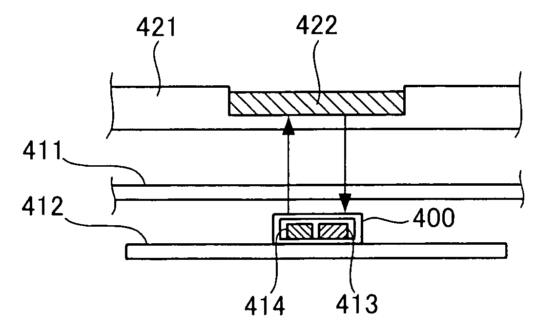
[0052]The lower part 41 contains a circuit board 412 in its case 411. A magnetic sensor 413 is mounted on the circuit board 412. Within the case 411 of the lower part 41, a magnet 414 is mounted securely alongside the magnetic sensor 413.

[0053]On the other hand, within the case 421 of the upper part 42, a magnetic plate 422 is attached securely to a position which faces both the magnetic sensor 413 and magnet 414 when the folding phone 40 is folded as s...

second embodiment

[0063]FIGS. 14 and 15 are schematic diagrams showing a folding phone which is a portable terminal device according to the present invention, where FIG. 14 shows an open state and FIG. 15 shows a closed state.

[0064]A folding phone 50 shown in FIGS. 14 and 15 consists of a lower part 51 and an upper part 52 pivotably supported by the lower part 51, as is the case with the folding phone according to the first embodiment shown in FIGS. 8 and 9. The upper part 52 pivots with respect to the lower part 51 in the directions of arrows A and B in FIG. 14 to switch between a closed state (folded state) (see FIG. 15) and open state (see FIG. 14).

[0065]The lower part 51 contains a circuit board 512 in its case 511. A magnetic sensor 513 is mounted on the circuit board 512. Within the case 511 of the lower part 51, a magnet 514 is mounted securely alongside the magnetic sensor 513.

[0066]On the other hand, the case 521 of the upper part 52 contains no element for open / close detection. Instead, the...

third embodiment

[0069]FIG. 16 is a schematic diagram showing a flip phone which is the present invention.

[0070]The flip phone 60 shown in FIG. 16 consists of a main part 61 and a flipper 62 pivotably supported by the main part 61. The flipper 62 opens and closes with respect to the main part 61 in the directions of arrows C and D.

[0071]The main part 61 contains a circuit board 612 in its case 611. A magnetic sensor 613 is mounted on that position of the circuit board 612 with which the flipper 62 overlaps when the flipper 62 is closed. Within the case 611 of the main part 61, a magnet 614 is mounted securely almost alongside the magnetic sensor 613 mounted on the circuit board 612.

[0072]Regarding the flipper 62, a plate member 621 itself composing the flipper 62 is made of magnetic material.

[0073]With this flip phone 60, again the opening and closing of the flipper 62 is detected according to the principle described with reference to FIGS. 10 and 11.

[0074]The flip phone 60 is thinner in overall thi...


PUM


Abstract

A portable terminal device which having a lower part; an upper part openable and closable in relation to the lower part; a magnet and a magnetic sensor attached to the lower part; and a magnetic plate which is attached to the upper part and leads the magnetic force of the magnet to the magnetic sensor, when the upper part is closed over the lower part.

Description

BACKGROUND OF THE INVENTION[0001]1. Field of the Invention[0002]The present invention relates to a portable terminal device which has an openable and closable part as well as to an open / close detector which detects the opening and closing of the part.[0003]2. Description of the Related Art[0004]Conventionally, various portable terminal devices such as folding phones are equipped with an open / close mechanism such as a folding mechanism that contains an open / close detector which detects the opening and closing of the open / close mechanism.[0005]For example, Japanese Reference Nos. 9-166405, 2002-125025 and 2002-204294 disclose a structure for use in a foldable device, such as a folding phone, equipped with a magnet on one of the parts which face each other when the device is folded, and a magnetic sensor on the other part, so that the magnetic sensor will detect magnetic force of the magnet when the device is folded.[0006]FIGS. 1 and 2 are schematic diagrams showing an open / close detec...

Claims


Application Information

Patent Timeline
Patent Type & Authority Patents(United States)
IPC IPC(8): H01R11/30H01R13/60H05K5/02G06F1/16H01H36/00H04B1/38H04M1/02
CPCH01H36/002H04M1/0235H04M1/0245H04M1/0214H01H36/0046H04M2250/12F16L21/08F16L25/0036
Inventor KAWAHIGASHI, YUTAKAYAMAMOTO, ATSUKOITOH, TOSHIYUKI
Owner FUJITSU LTD
Why Eureka
Try Eureka