Compliant pin and electrical connector utilizing compliant pin

a technology of compliant pins and electrical connectors, applied in the direction of coupling contact members, coupling device connections, coupling/insulating coupling contact members, etc., can solve the problems of short printed circuits, insufficient coating for all circuit boards, and need an addition component and additional manufacturing step, so as to reduce the amount of shavings that scatter on the circuit board, the effect of shortening the circui

Inactive Publication Date: 2006-07-11
TYCO ELECTRONICS JAPAN GK
View PDF9 Cites 22 Cited by
  • Summary
  • Abstract
  • Description
  • Claims
  • Application Information

AI Technical Summary

Benefits of technology

[0007]It is an object of the invention to provide a compliant pin that is press-fit into a compliant pin receiving aperture of a circuit board wherein the amount of shavings that scatter on the circuit board is reduced without increasing the number of components or manufacturing steps and an electrical connector using the same. It is further an object of the invention to provide a compliant pin that is press-fit into a compliant pin receiving aperture of a circuit board wherein shavings generated from the press-fitting are miniaturized so that shorting among circuits on the circuit board and among electronic devices in prevented and an electrical connector using the same.

Problems solved by technology

The shavings may be scattered on the circuit board and therefore there is a possibility that the scattered shavings will short printed circuits on the circuit board or electronic components provided thereon.
However, the coating is not necessarily administered for all circuit boards.
Both of these techniques have the disadvantage that they require an addition component and an additional manufacturing step.
Thus, the costs of manufacturing are increased and the manufacturing process is more difficult in the above-mentioned techniques.

Method used


Image

  • Compliant pin and electrical connector utilizing compliant pin
  • Compliant pin and electrical connector utilizing compliant pin
  • Compliant pin and electrical connector utilizing compliant pin

Examples


Embodiment Construction

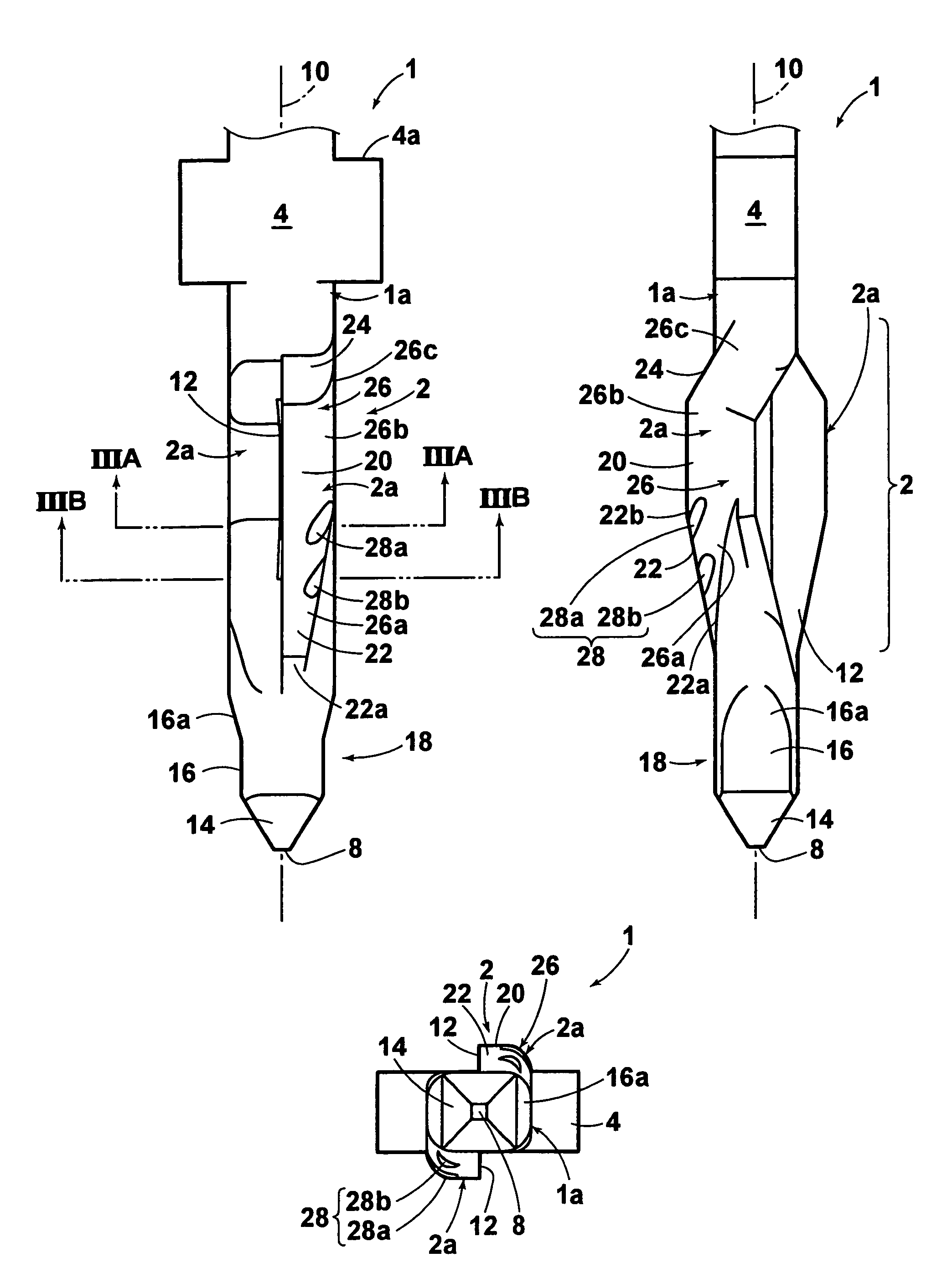
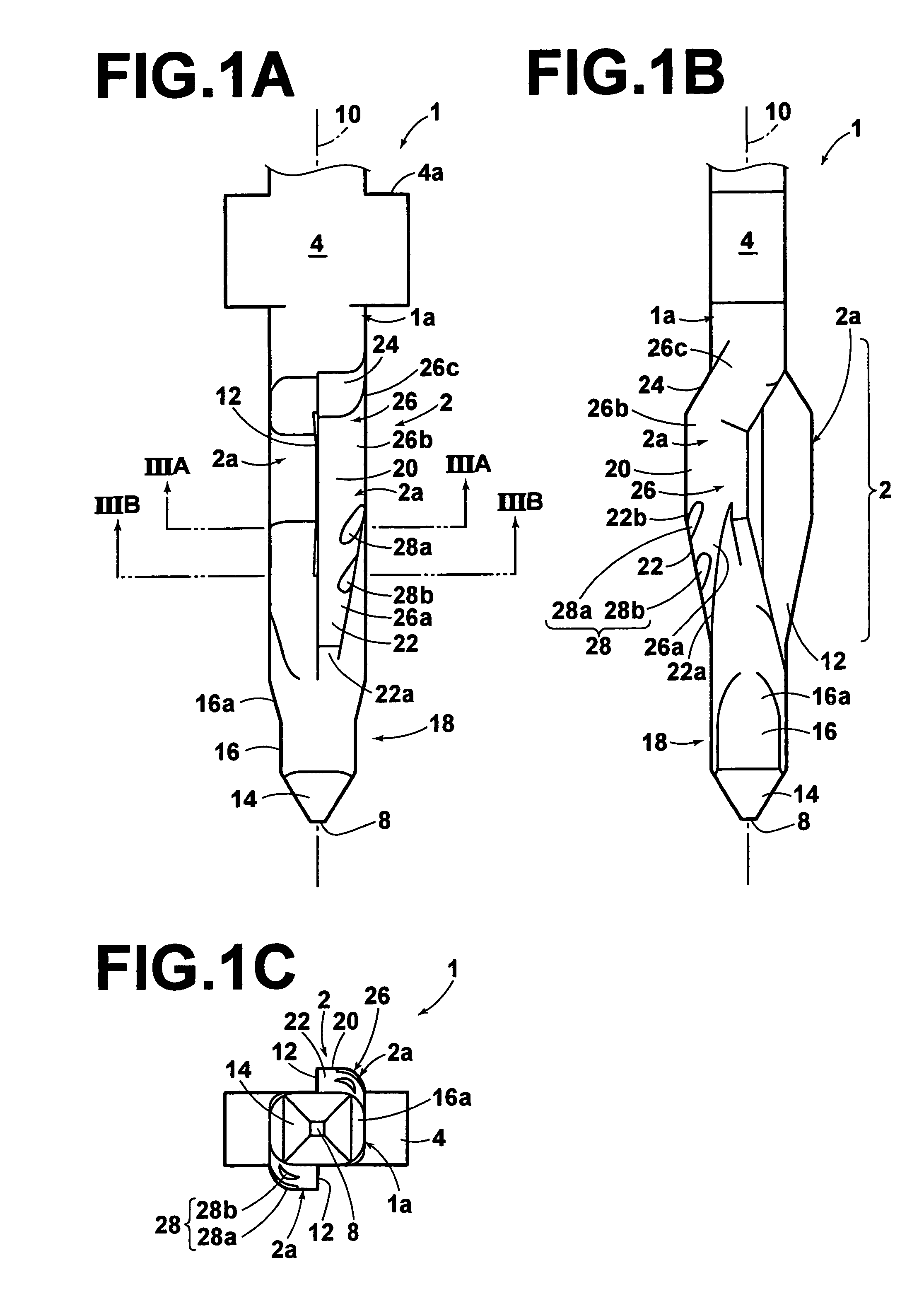
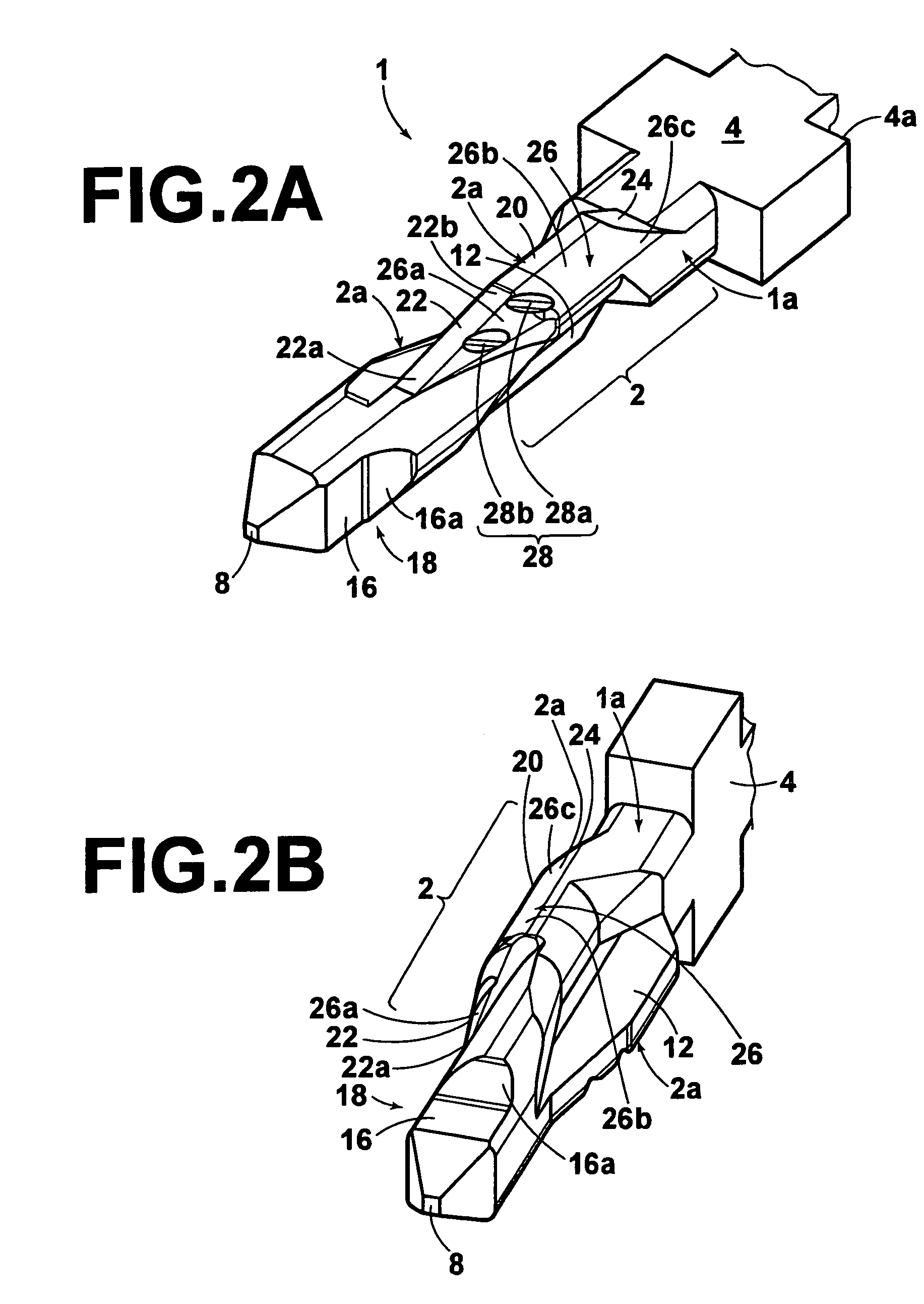
[0019]FIGS. 1A–3B show a compliant pin 1 according to the invention. The compliant pin 1 is substantially pin-shaped and is formed, for example, by stamping a single metal plate. The compliant pin 1 may be formed, for example, from an alloy, such as copper, so that the compliant pin 1 has conductive properties. The alloy may then be plated with a first plating material, such as nickel. A second plating material, such as tin, may then be administered over the first plating material.

[0020]The thickness of the first and second plating materials may be, for example, 08 μm to 1.5 μm. It will be appreciated by those skilled in the art, however, that the first and second plating materials may be any metal that has conductive properties and is corrosion resistant, such as gold.

[0021]As shown in FIGS. 2A–2B and 4, the compliant pin 1 has a substantially rectangular cross-section and comprises a press-fit portion 2, a pressing portion 4, a contact portion 6, and an end portion 18. As shown in...


PUM


Abstract

A compliant pin comprises a contact portion, an end portion, and a press-fit portion. The press-fit portion is arranged between the contact portion and the end portion. The press-fit portion is deformable in a radial direction. The press-fit portion has a first tapered surface with a first end and a second end. The first tapered surface has recesses for receiving shavings generated when the compliant pin is press-fit.

Description

FIELD OF THE INVENTION[0001]The invention relates to a compliant pin provided with recesses for receiving shavings formed when the compliant pin is press-fit into a compliant pin receiving aperture in a circuit board and an electrical connector using the same.BACKGROUND OF THE INVENTION[0002]Compliant pins are slightly elastically deformable in a radial direction. When press-fit portions of the compliant pins are pressed into compliant pin receiving apertures of a circuit board, because the compliant pin receiving apertures have slightly smaller diameters than the compliant pins, the compliant pins are fixed to the circuit board due to elastic deformation. Favorable electrical connections can thereby be established without soldering.[0003]Inner surfaces of the compliant pin receiving apertures are generally plated with a material, such as copper. The compliant pins are generally plated across their entire surfaces with a material, such as tin. Because the plating of the compliant pi...

Claims


Application Information

Patent Timeline
Patent Type & Authority Patents(United States)
IPC IPC(8): H01R13/42
CPCH01R12/585H01R13/03
Inventor KAWAHARA, YUZOYAMAGAMI, HIDEHISA
Owner TYCO ELECTRONICS JAPAN GK
Why Eureka
Try Eureka