Multiple facet joint replacement

a facet joint and multiple technology, applied in the field of surgical devices, can solve the problems of limiting the range of motion, causing debilitating pain, and affecting the function of the spine,

Inactive Publication Date: 2006-07-11
GLOBUS MEDICAL INC
View PDF338 Cites 259 Cited by
  • Summary
  • Abstract
  • Description
  • Claims
  • Application Information

AI Technical Summary

Benefits of technology

[0022]The above, and other, objects, features and advantages of the present invention will become appa

Problems solved by technology

Traumatic, inflammatory, metabolic, synovial, neoplastic and degenerative disorders of the spine can produce debilitating pain that can have severe socioeconomic and psychological effects.
For example, it has been shown that spine fusion decreases function by limiting the range of motion for patients in flexion, extension, rotation, and lateral bending.
Furthermore, it has been shown that spine fusion creates increased stresses and, therefore, accelerated degeneration of adjacent non-fused motion segments.
Additionally, pseudoarthrosis, as a result of an incomplete or ineffective fusion, may reduce or even eliminate pain relief for the patient.
However, the artificial discs proposed to date do not fully address the mechanics of motion of the spinal column.
Additionally, at least in the case of surface replacements for osteoarthritis femoral heads, the capping of articular bone ends has proven to lead to clinical failure by means of mechanical loosening.
The clinic

Method used


Image

  • Multiple facet joint replacement
  • Multiple facet joint replacement
  • Multiple facet joint replacement

Examples


Embodiment Construction

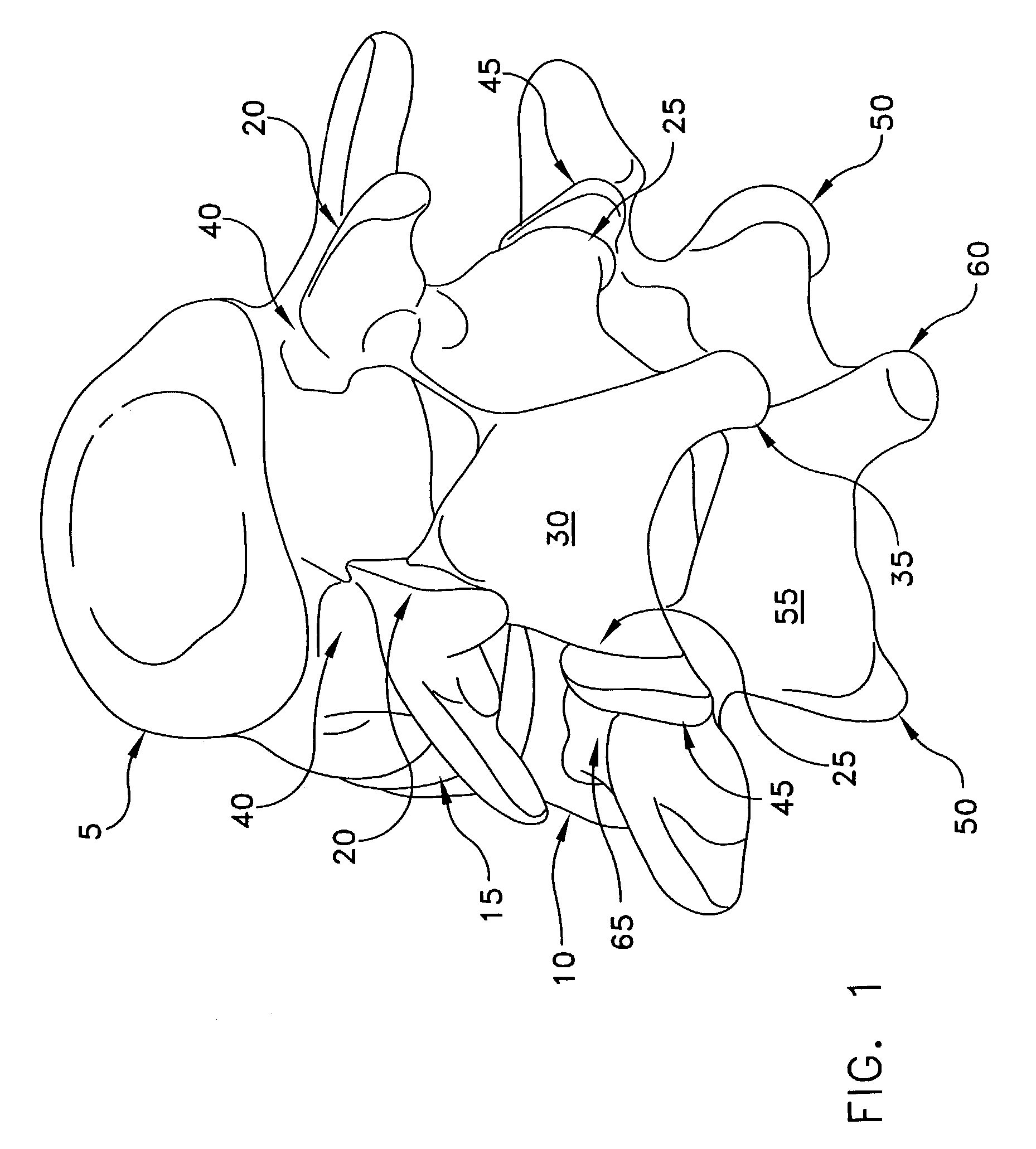
[0040]Referring first to FIG. 1, there is shown a superior vertebra 5 and an inferior vertebra 10, with an intervertebral disc 15 located in between. Vertebra 5 has superior facets 20, inferior facets 25, a lamina (also sometimes referred to as a posterior arch) 30, a spinous process 35, and pedicles 40. Vertebra 10 has superior facets 45, inferior facets 50, a posterior arch 55, a spinous process 60, and pedicles 65 (only one of which is seen in FIG. 1).

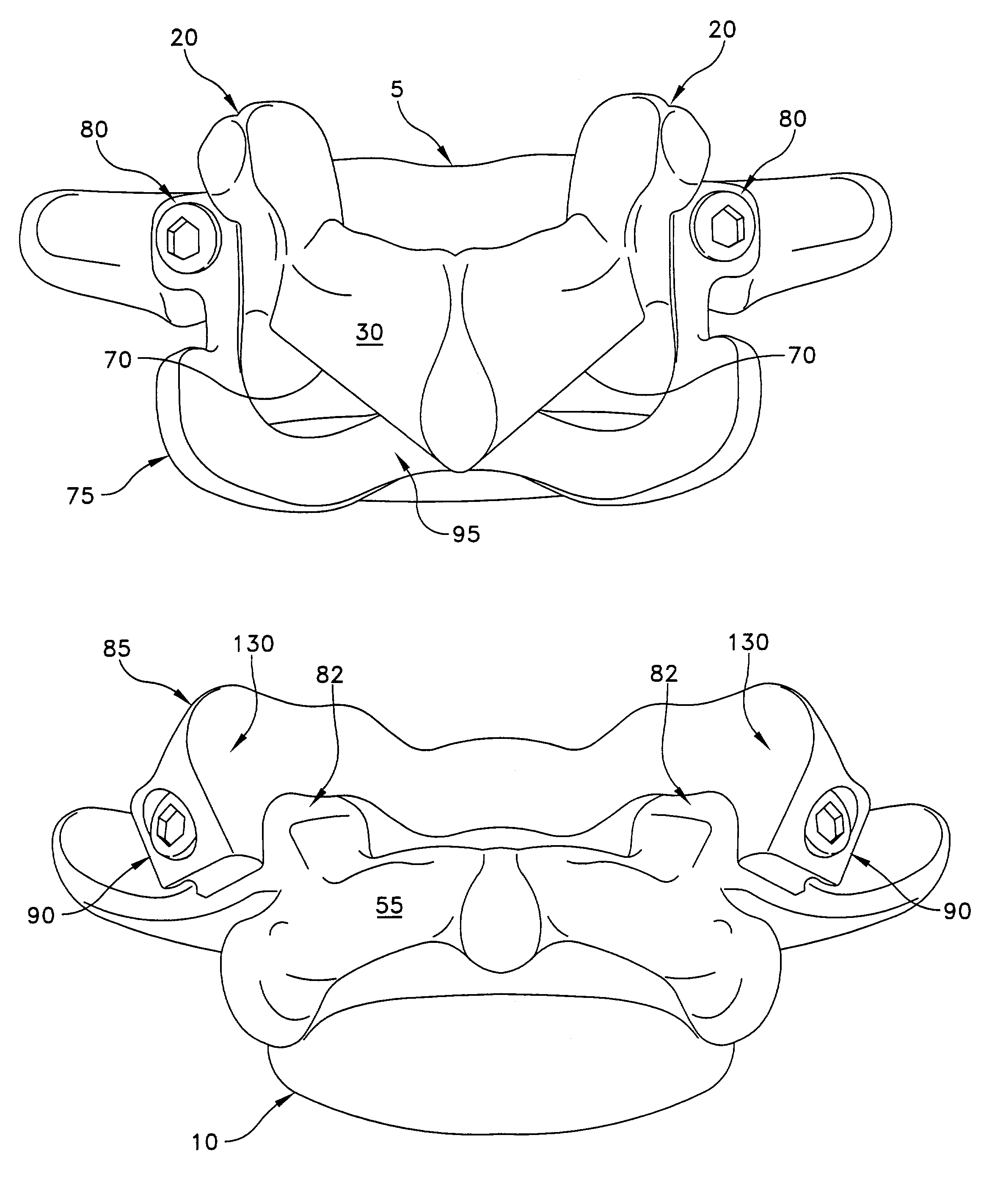
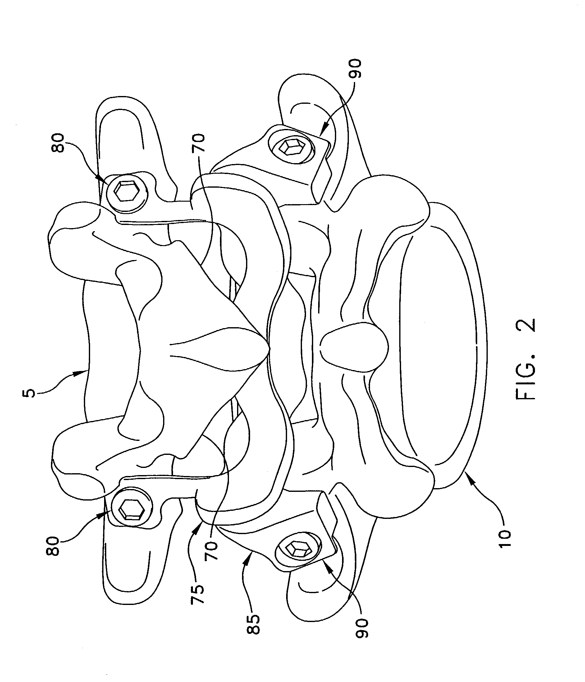
[0041]Referring now to FIG. 2, the left and right inferior facets 25 of vertebra 5 have been resected at 70 and a bilateral inferior facet prosthesis 75 has been attached to vertebra 5 using screw fasteners80. Similarly, the left and right superior facets 45 of vertebra 10 have been resected at 82 (FIG. 7) and a bilateral superior facet prosthesis 85 has been attached to vertebra 10 using screw fasteners 90.

[0042]In FIG. 3 it can be appreciated that bilateral inferior facet prosthesis 75 replicates the natural anatomy when compared ...


PUM


Abstract

A prosthesis for the replacement of multiple diseased or traumatized spinal facets comprises a portion that replaces at least a bony portion of the facets to be replaced and where the prosthesis attaches to the vertebra in a manner that does not require attachment to, or abutment against, the lamina. Multiple configurations of the prosthesis provide for replacement of the two inferior facets, the two superior facets, a superior and inferior facet, or all four facets. A method of installing the prosthesis is provided that is comprised of the steps of resecting at least a portion of the facets that carry the diseased or traumatized spinal facets and attaching the prosthesis in a manner that does not require attachment or abutment against the lamina.

Description

[0001]This is a continuation of prior U.S. patent application Ser. No. 09 / 736,103, filed Dec. 13, 2000 by E. Marlowe Goble et al. for MULTIPLE FACET JOINT REPLACEMENT now U.S. Pat. No. 6,565,605.BACKGROUND OF THE INVENTION[0002]1. Field of the Invention[0003]The present invention relates to surgical devices and methods to replace a damaged, diseased, or otherwise painful spinal facet joint.[0004]2. Description of Related Art[0005]Traumatic, inflammatory, metabolic, synovial, neoplastic and degenerative disorders of the spine can produce debilitating pain that can have severe socioeconomic and psychological effects. One of the most common surgical interventions today is arthrodesis, or spine fusion, of one or more motion segments, with approximately 300,000 procedures performed annually in the United States. Clinical success varies considerably, depending upon technique and indications, and consideration must be given to the concomitant risks and complications. For example, it has be...

Claims


Application Information

Patent Timeline
IPC IPC(8): A61F2/44A61B17/56
CPCA61F2/4405Y10S606/91Y10S606/907
Inventor GOBLE, E. MARLOWEFALLIN, T. WADEHOY, ROBERT W.
Owner GLOBUS MEDICAL INC
Why Eureka
Try Eureka