Facet joint replacement

a facet joint and joint technology, applied in the field of surgical devices, can solve the problems of increasing the stress of spine fusion, accelerating the degeneration of adjacent non-fused motion segments, and causing severe socioeconomic and psychological effects, and achieves excellent long-term fixation strength, improved quality of attachment of prosthesis, and precise press fit

Inactive Publication Date: 2005-04-14
FACET SOLUTIONS
View PDF99 Cites 158 Cited by
  • Summary
  • Abstract
  • Description
  • Claims
  • Application Information

AI Technical Summary

Benefits of technology

[0100] The present invention has numerous advantages over the prior art. One advantage is that the quality of attachment of the prosthesis is improved. The present invention provides a precise press fit into bones, as opposed to relying on prosthetic surfaces mating with highly complex and variable external surfaces of the vertebra, such as the posterior arch or facet. Another advantage is that the optional porous coating is placed into interior bone spaces where porous coatings have proven to achieve

Problems solved by technology

Traumatic, inflammatory, metabolic, and degenerative disorders of the spine can produce debilitating pain that can have severe socioeconomic and psychological effects.
Furthermore, Khoo and Nagata have shown that spine fusion creates increased stresses and, therefore, accelerated degeneration of adjacent non-fused motion segments.
Additionally, pseudoarthrosis, as a result of an incomplete or ineffective fusion, may reduce or even eliminate the desired pain relief for the patient.
However, the artificial discs proposed to da

Method used


Image

  • Facet joint replacement
  • Facet joint replacement
  • Facet joint replacement

Examples


Embodiment Construction

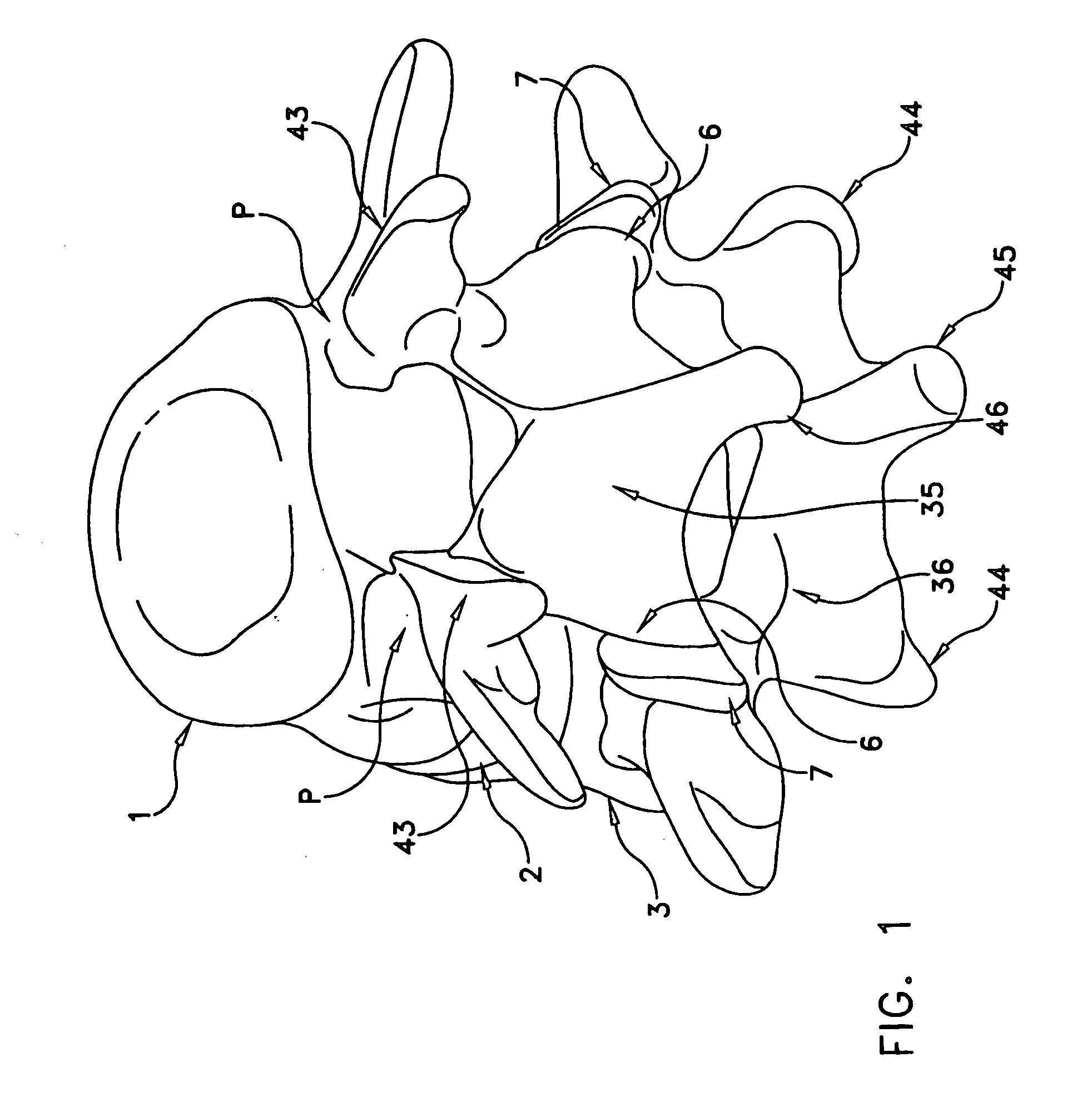
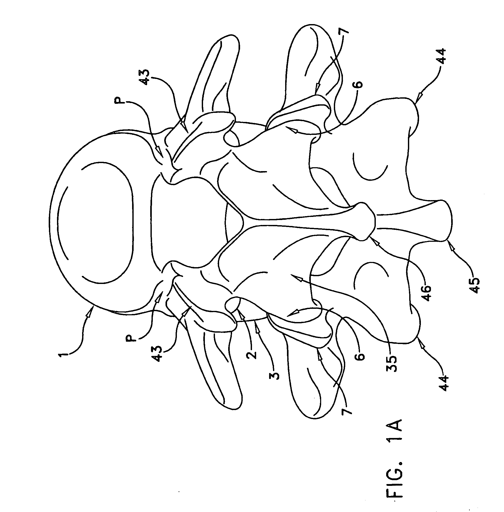
[0150] Referring now to FIGS. 1 and 1A, there is shown a superior vertebra 1 and an inferior vertebra 3, with an intervertebral disc 2 located in between. Vertebra 1 has superior facets 43, inferior facets 6, posterior arch (or lamina) 35 and spinous process 46. Vertebra 3 has superior facets 7, inferior facets 44, posterior arch (or lamina) 36 and spinous process 45.

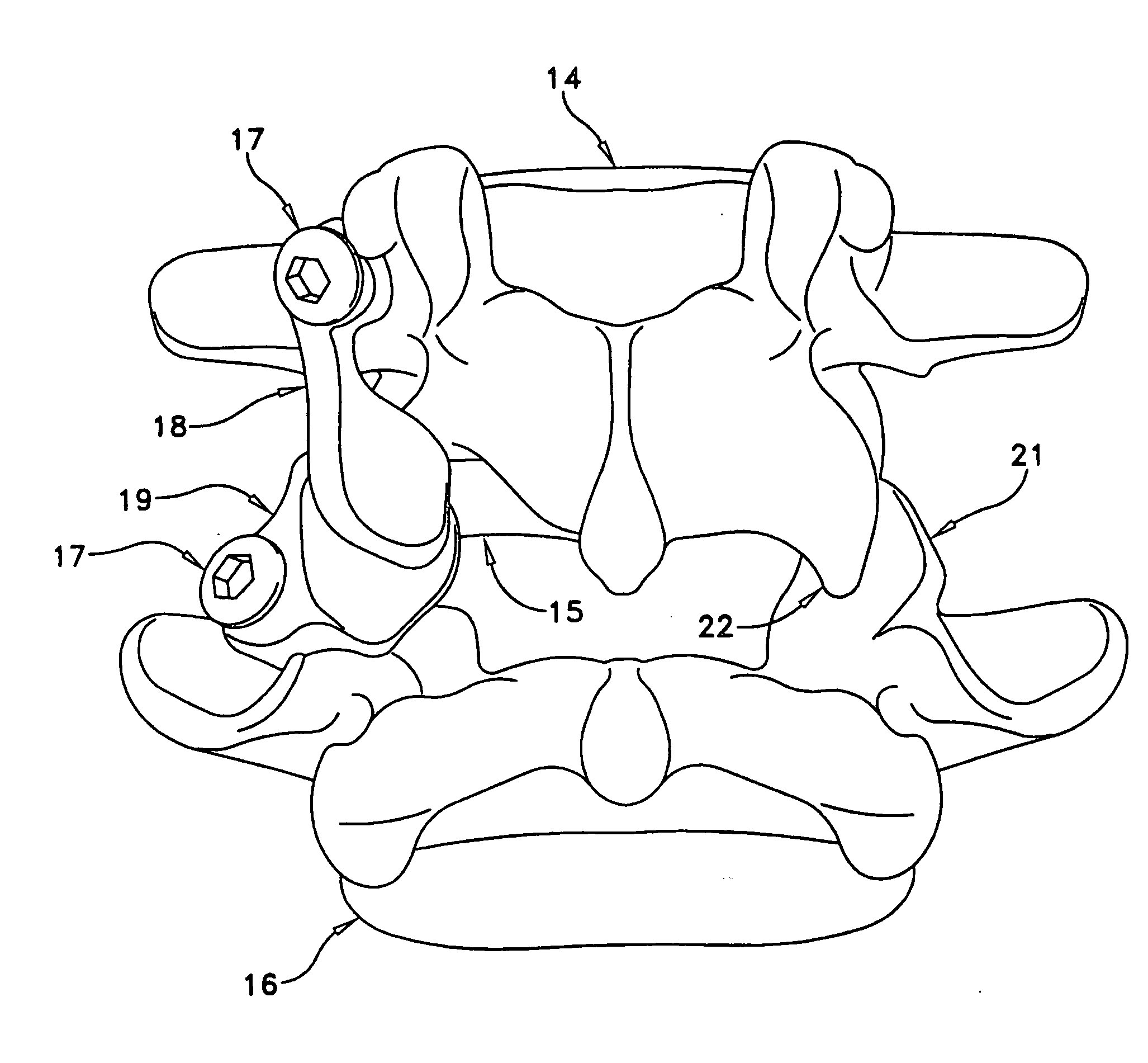
[0151] Referring now to FIG. 2, the left inferior facet 6 of vertebra 1 shown in FIG. 1 and FIG. 1A has been resected and inferior facet prosthesis 4 has been attached to vertebra 1. Similarly, the left superior facet 7 of vertebra 3 has been resected and a superior facet prosthesis 5 has been attached to vertebra 3.

[0152]FIG. 3 illustrates a dorsal view of the elements shown in FIG. 2. It can be appreciated that inferior facet prosthesis 4 replicates the natural anatomy when compared to the contralateral inferior facet 6 of vertebra 1. Similarly, it can be appreciated that superior facet prosthesis 5 replicates the n...


PUM


Abstract

A prosthesis for the replacement of at least a portion of the bone of a facet located on a mammalian vertebra, comprising: an articulating surface that articulates with another facet; a bone contacting surface that contacts a surface of the vertebra, the articulating surface being connected to the bone contacting surface; and a fixation element that attaches the bone contacting surface to the vertebra, the fixation element being adapted for implantation into an interior bone space of a pedicle of the vertebra; wherein the prosthesis is configured so that no portion of the prosthesis contacts the posterior arch of the vertebra.

Description

REFERENCE TO PENDING PRIOR APPLICATIONS [0001] The present application claims the benefit of: [0002] (i) pending prior U.S. patent application Ser. No. 10 / 421,078, filed Apr. 23, 2003 by E. Marlowe Goble et al. for FACET JOINT REPLACEMENT (Attorney's Docket No. MED-1 CON); and [0003] (ii) pending prior U.S. Provisional Patent Application Ser. No. 60 / 505,199, filed Sep. 23, 2003 by E. Marlowe Goble et al. for FACET JOINT REPLACEMENT (Attorney's Docket No. MED-1 CIP PROV). [0004] The two above-identified documents are hereby incorporated herein by reference.BACKGROUND OF THE INVENTION [0005] 1. Field Of The Invention [0006] The present invention relates to surgical devices and methods to replace a damaged, diseased, or otherwise painful spinal facet joint. [0007] 2. Description Of Related Art [0008] Traumatic, inflammatory, metabolic, and degenerative disorders of the spine can produce debilitating pain that can have severe socioeconomic and psychological effects. One of the most comm...

Claims


Application Information

Patent Timeline
IPC IPC(8): A61FA61F2/44
CPCA61F2/4405A61B17/7062A61B17/7064A61B17/844A61F2/4637A61F2002/448
Inventor FALLIN, T. WADEGOBLE, E. MARLOWEHOY, ROBERT W.JUSTIN, DANIEL F.CHERVITZ, ALANPAGANELLI, JUDE V.TRIPLOTT, DAN
Owner FACET SOLUTIONS
Why Eureka
Try Eureka