Electric rotating machine and manufacturing process thereof

a technology of rotating machines and manufacturing processes, which is applied in the direction of manufacturing stator/rotor bodies, magnetic circuit rotating parts, and shape/form/construction of magnetic circuits, etc., can solve the problems of high working accuracy of pole cores and permanent magnets, reasonable cost as a whole, and the accuracy of permanent magnets can be precisely mounted and held. , to achieve the effect of high working accuracy, simple configuration of magnet holding parts, and reasonable cos

Active Publication Date: 2005-05-26
MITSUBISHI ELECTRIC CORP
View PDF8 Cites 17 Cited by
  • Summary
  • Abstract
  • Description
  • Claims
  • Application Information

AI Technical Summary

Benefits of technology

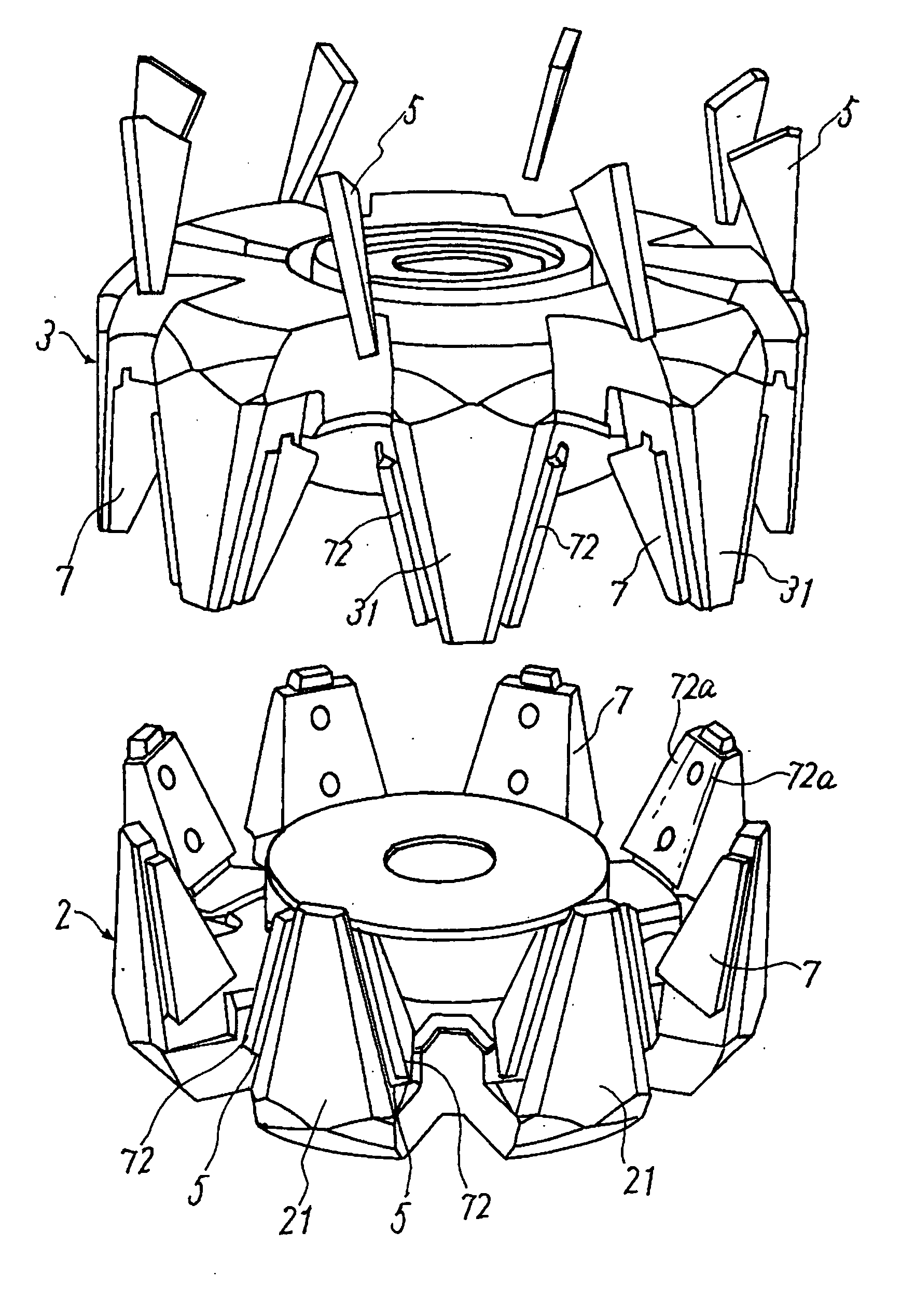
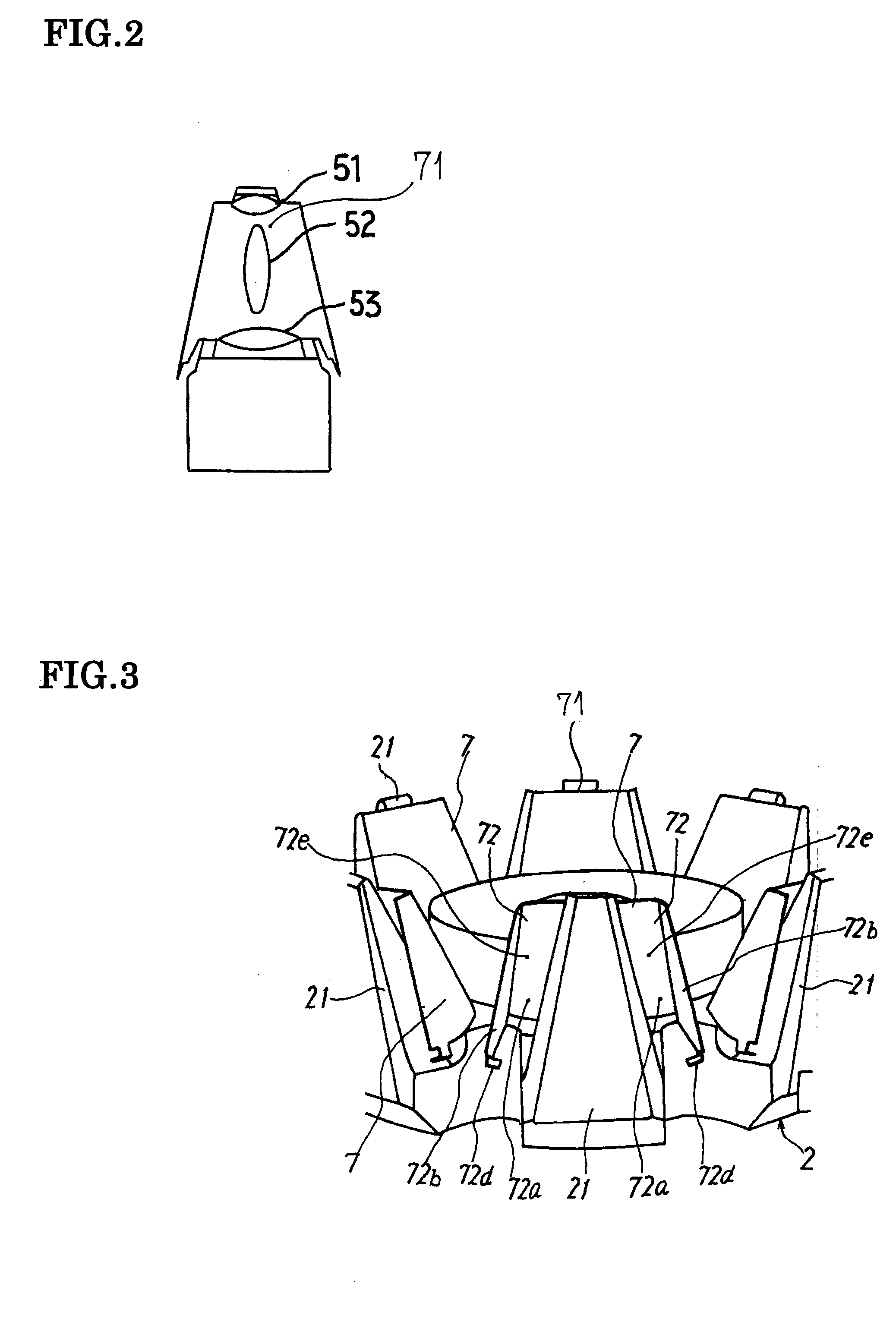
[0017] In the electric rotating machine of above arrangement according to the invention, since a magnet-holding member is separately mounted on each of the claw-shaped magnetic poles, configuration of the magnet holding part is simple and can be manufactured at reasonable cost. Further, a permanent magnet can be exactly mounted and held without high working accuracy of the pole core and the permanent magnet. Therefore, any cutting of the pole core is not required but forging thereof is sufficient, resulting in manufacture at reasonable cost as a whole. In addition, to mount the permanent magnet on the magnet mounting part of the magnet holding member, it is possible to bend the magnet holding member and/or charge with any adhesive, in which case the permanent magnet can be more firmly fixed to the magnet mounting part. Further, in the case of mounting the permanent magnet by bending the magnet-holding member, replacement of the permanent magnet can be carried out by unbending the bent part.
[0018] In the case of fixing the mentioned magnet-holding member to each claw-shaped magnetic pole of the two pole cores, the permanent magnet can be shaped conforming to the shape of the side face of each of the claw-shaped magnetic poles. As a result, leakage flux from between the claw-shaped magnetic poles can be efficiently prevented by the permanent magnet. Further, any part not useful for the prevention of leakage flux can be omitted, and therefore cost of materials can be reduced. Furthermore, since each individual permanent magnet can be small-sized, centrifugal force applied to each permanent magnet becomes small, thus durability of the rotor being improved.
[0019] When fixing the magnet-holding member to the claw-shaped magnetic poles by welding, fixation strength becomes larger and exact fixation is achieved. When fixing by caulking, the fixation is easy and less expensive. Further, when fixing by adhesion, the magnet holding member and the pole cores can be fixed

Problems solved by technology

Further, a permanent magnet can be exactly mounted and held without high working accuracy of the pole core and the permanent magnet.
Therefo

Method used


Image

  • Electric rotating machine and manufacturing process thereof
  • Electric rotating machine and manufacturing process thereof
  • Electric rotating machine and manufacturing process thereof

Examples


embodiment 2

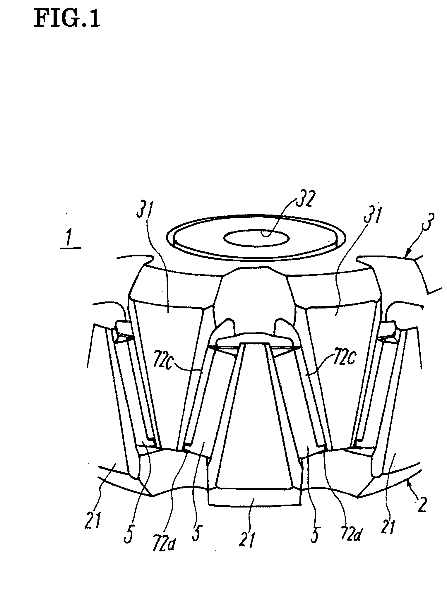
[0043]FIG. 6 is a perspective view showing a structure of a rotor of an electric rotating machine according to Embodiment 2 of the invention, and in which the same reference numerals indicates the same or like parts corresponding to the foregoing Embodiment 1 shown in FIGS. 1 to 3.

[0044] This Embodiment 2 is characterized in that the magnet-holding member 7 is fixed to each of the claw-shaped magnetic poles 21, 31 of the pair of pole cores 2, 3. Arrangement of the magnet-holding member 7 is basically the same as in the foregoing Embodiment 1.

[0045] However, in this Embodiment 2, width of the extending part 72a of each magnet mounting part 72 in circumferential direction is not larger than a half of that in the foregoing Embodiment 1. Accordingly, thickness of the permanent magnet 5 is also not larger than a half of that in the foregoing Embodiment 1, and the permanent magnet 5 is shaped conforming to the side face of each of the claw-shaped magnetic poles 21, 31. Accordingly, at t...


PUM


Abstract

In an electric rotating machine, a rotor can be manufactured relatively easily at reasonable cost without high working accuracy for pole cores, and a permanent magnet can be assembled without impairing cooling efficiency of the rotor. A magnet-holding member 7 is separately fixed to a claw-shaped magnetic pole 21 of at least one of a pair of pole cores 2, 3; each magnet-holding member 7 is provided with a magnet mounting part 72 on which a permanent magnet 5 is mounted on two sides of the claw-shaped magnetic pole 21 in circumferential direction; and each magnet mounting part 72 is formed so as to be located between the claw-shaped magnetic poles 21, 31 engaged with each other.

Description

BACKGROUND OF THE INVENTION [0001] 1. Field of the Invention [0002] The present invention relates to an electric rotating machine having a rotor provided with plural permanent magnets, and to a manufacturing method of the electric rotating machine. [0003] 2. Description of the Related Art [0004] In a rotor of the conventional electric rotating machines, to facilitate adjustment of magnetic flux amount, a number of claw-shaped magnetic poles covering a rotor coil disposed at a predetermined pitch along the circumferential direction form a pair of pole cores, and the pairs of pole cores are oppositely disposed so that the mentioned claw-shaped magnetic poles are engaged with each other, thus a rotor core being formed. [0005] In the electric rotating machine of this type, a current is applied to a rotor coil to magnetize the pole core. To operate as a generator, a rotating force is applied from outside such as engine to the rotor thereby causing a stator coil to generating an electromo...

Claims


Application Information

Patent Timeline
IPC IPC(8): H02K1/24H02K1/00H02K1/22H02K1/27H02K3/00H02K15/03H02K19/22H02K19/26H02K21/04
CPCH02K21/044
Inventor MAEDA, NAOHIDEASAO, YOSHIHITOFUJITA, MASAHIKO
Owner MITSUBISHI ELECTRIC CORP
Why Eureka
Try Eureka