Thermostated block with heat-regulating devices

a technology of heat-regulating devices and thermostated blocks, which is applied in the direction of material heat development, instruments, laboratory glasswares, etc., can solve the problems of reducing the thermal impedance affecting the temperature of the thermostated block solely at its ends, and affecting the temperature of the thermostated block at the middle, etc., to achieve a shallow temperature gradient, improve thermal impedance, and improve thermal impedance

Inactive Publication Date: 2006-07-11
EPPENDORF AG
View PDF22 Cites 34 Cited by
  • Summary
  • Abstract
  • Description
  • Claims
  • Application Information

AI Technical Summary

Benefits of technology

[0009]The temperature profile across the thermostated block, namely the particular temperature gradient, does not always correspond to the desired temperature profile. Deviations arise in particular at the ends of the thermostated block where the effect of the adjacent heat-regulating devices is less and thus the temperature gradient is shallower. Using such segments of different thermal conductivities allows correcting the temperature curve. In particular, a higher temperature gradient may be achieved using a higher thermal impedance, and thereby the shallow gradients at the ends may be corrected.
[0010]In an advantageous manner, the segments of the thermostated block increase in thermal impedance from its center toward its edge. As a result the temperature profile can be linearized.
[0011]The segments can be form as grooves which by merely reducing the local, material cross-section produce a higher thermal impedance. In contrast to the known cross-boreholes found for such purposes in the initially cited design of the state of the art, the invention's configuration offers easier manufacture and a more advantageous geometry between wells in the form of recesses.
[0012]Dividing the contact side of the block longitudinally and transversely into zones making contact with separate heat-regulating devices is advantageous. The heat regulating devices distributed across the surface may be operated in a variety of ways. Laterally adjacent heat-regulating devices may be operated to be identically thermostating so that a temperature gradient is set up in the longitudinal or in the transverse direction of the thermostated block. Illustratively, a gradient may be set up in a thermostated block at different temperature levels in different directions. Also, the heat-regulating devices each may be operated differently so that a temperature gradient may be set up as well in the x-direction as in the y-direction, for instance with different temperature gradients in the two directions.
[0013]Two different types of laboratory vials may be used without having to convert the laboratory thermostats. Even mixed outfitting is possible. The large number of closely adjoining recesses in the form of wells allows lowering the mass of the thermostated block. As a result the heat capacity of the block is lowered and the temperature may be raised more rapidly to the desired temperature. Moreover it is also possible to make the thermostated block thinner toward its wells side whereby the heat between the heat-regulating devices preferably follows a path through a plate-region of the thermostated block adjacent to the contact side, and as a result the desired temperature can be set very accurately and uniformly. Thereby, the wells of one type are made to match a predetermined grid arrangement of vials. Hence, vials also may be used which illustratively are integrated into a continuous plate configuration. The desired thinning of the upper part of the thermostated block situated toward the receiving side may be enhanced by additional holes between the wells. A continuous plate of the thermostated block, two different types of running continuously underneath the wells and holes, increases the uniformity of the temperature setting. Segments having higher thermal impedances as are present in the initially cited conventional design in the form of boreholes may be used to correct the desired temperature profile. Advantageously such segments are in the form for instance of grooves running from the contact side and illustratively meandering between the wells and the holes.
[0014]The block together with another heat regulating device can be made displaceable relative to a plate holder supporting the vials and can be exchangeably moved to a position of alignment of the wells relative to the vials. As in the known design, they make it possible to subject the containers sequentially to various thermostated blocks thermostated at different levels and each having either a temperature gradient or a temperature constant across its surface. To allow sideways motion, the thermostated blocks may be mounted in a laterally displaceable carriage. They also may be mounted in a rotor for that purpose, the rotor illustratively rotating like a lazy Susan in a plane parallel to the holding means. Preferably, they are rotated together with a rotor about a shaft parallel to the holding means to allow especial compactness. The blocks may be displaced to move away from the rotor, or preferably the rotor is moved to effect separation as a whole.

Problems solved by technology

Controlling the temperature of the thermostated block solely at its ends, however, has a drawback.
When turning the apparatus ON or when the temperature to be set in the thermostated block changes, the thermostating time delays to the desired equilibrium are substantial on account of the two-end thermostating.
Furthermore, the temperature at the middle of the thermostated block may deviate from the desired temperature profile due to environmental effects.

Method used


Image

  • Thermostated block with heat-regulating devices
  • Thermostated block with heat-regulating devices
  • Thermostated block with heat-regulating devices

Examples


Embodiment Construction

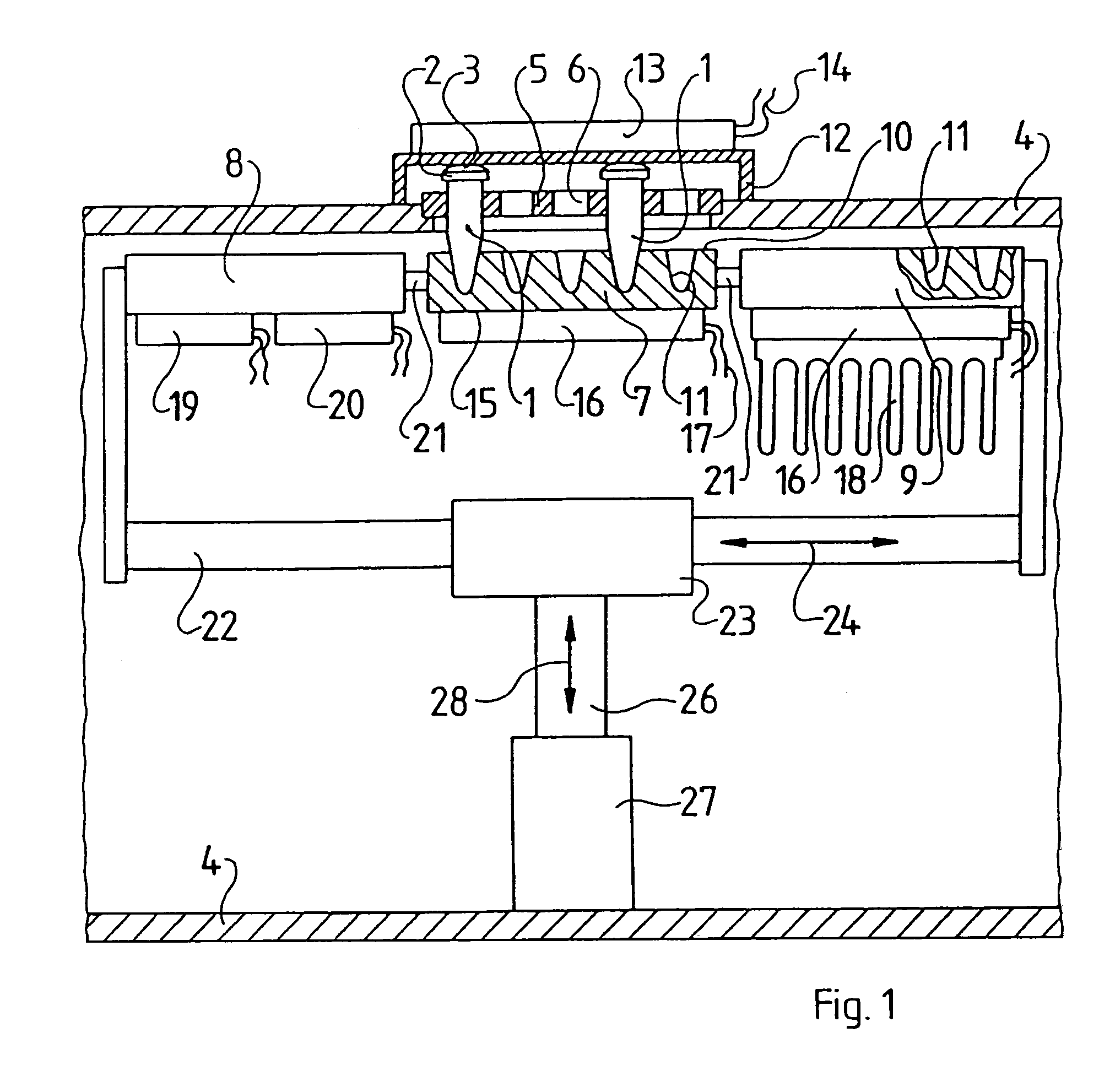
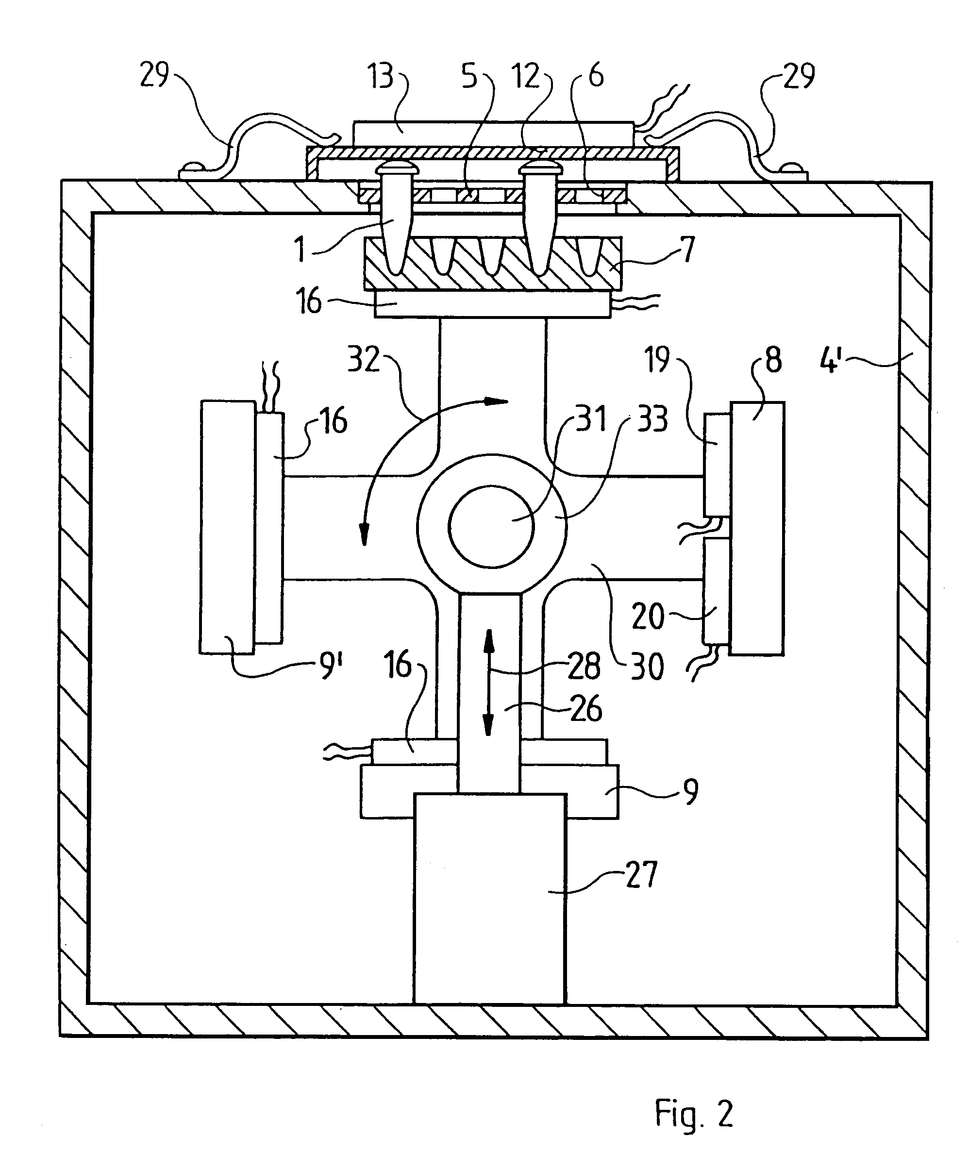
[0025]FIG. 1 shows a laboratory thermostat which is especially appropriate for the PCR process. Sample liquids, for instance mixtures of reactions, are to be sequentially set to different temperatures.

[0026]For that purpose, the sample liquids are present in vials 1 which in the embodiment shown are commercial thin-walled plastic reaction vials. Each vial comprises a cylindrical part which, as shown in FIG. 1, tapers conically at its lower end region receiving the sample liquid. The upper edge comprises a collar 2 and an elastically deforming lid 3 closing vial 1.

[0027]The laboratory thermostat shown comprises an enclosing housing 4 receiving at its top side a perforated plate acting as a holder 5 with holes 6 keeping the vials 1 in place and securing the vials at their collars 2 against dropping out of the plate.

[0028]A thermostated block 7 is mounted underneath the holding plate 5 and comprises at its upper side 10, herein called the wells side, wells 11 having shapes correspondin...


PUM

PropertyMeasurementUnit
temperatureaaaaaaaaaa

Abstract

The invention concerns a thermostated block for laboratory thermostats and comprising wells at a wells side to receive and make large-area contact with the parts of vials filled with sample liquids and comprising at least two heat regulating devices contacting the thermostated block in thermally conducting manner to generate different temperatures at different sites of the thermostated block, said block being characterized in that the heat regulating devices are in large-area contact with adjoining zones of the contact side opposite the wells side of the thermostated block.

Description

RELATED APPLICATION[0001]This application is a continuation of application Ser. No. 09 / 101,124 filed Jun. 30, 1998 now U.S. Pat. No. 6,767,512.BACKGROUND OF THE INVENTION[0002]The invention relates to a thermostated block for laboratory thermostats having wells to receive and make large-area contact with segments of liquid sample filled vials and having heat regulating devices making good thermal contact with the block to generate different temperatures at different sites of the block.[0003]Such a thermostated block is known from U.S. Pat. No. 5,525,300. Two heat-regulating devices in thermal contact with the thermostated block at two of its opposite ends heat it at one end and cool it at the other. A thermal flow runs longitudinally between the heat regulating devices through the thermostated block so that a temperature profile is generated in the longitudinal block direction, resulting in different temperatures. A thermostated block generating such a temperature gradient allows as...

Claims


Application Information

Patent Timeline
Patent Type & Authority Patents(United States)
IPC IPC(8): B01L9/00C12N15/09B01L3/00B01L7/00C12M1/00C12M1/38C12Q1/68G01N35/00G05D23/19
CPCB01L3/50851B01L3/50853B01L7/52B01L7/525B01L7/54B01L7/5255G01N2035/00366B01L2200/023B01L2300/1822
Inventor LURZ, WERNERBRUST, RUEDIGERJODIES, DIETMARTENNSTEDT, ERNST
Owner EPPENDORF AG
Why Eureka
Try Eureka