Method of plasma etching a deeply recessed feature in a substrate using a plasma source gas modulated etchant system

a plasma source gas and etching technology, applied in the direction of basic electric elements, semiconductor/solid-state device manufacturing, electric devices, etc., can solve the problems of difficult combination with a smooth sidewall surface, difficult to achieve satisfactory results, and strict control of the etch profile, so as to reduce the amount of microloading, improve the etch process, and improve the effect of sidewall smoothness

Inactive Publication Date: 2006-07-11
APPLIED MATERIALS INC
View PDF14 Cites 20 Cited by
  • Summary
  • Abstract
  • Description
  • Claims
  • Application Information

AI Technical Summary

Benefits of technology

[0017]Use of a stabilizing etchant continuously during the etch process enables a simplified, streamlined etch process; enables the formation of vertical sidewalls on recess etched features, while providing improved sidewall smoothness over previously known process methods; and, reduces the amount of microloading which occurs when dense and isolated features are etched on the same substrate during the same etch process.

Problems solved by technology

Strict control of the etch profile is required for these new, complex devices to perform satisfactorily.
Obtaining a controlled sidewall taper angle of 85° to 92° in combination with a smooth sidewall surface has proved a difficult task in many instances.
However, to obtain a vertical sidewall, it is necessary to control the incoming ions so that they strike the bottom of the feature being etched, but not the already etched surfaces extending above the bottom of the feature.
However, this increase in process complexity is said to address or reduce various problems in the etch process described in the Laermer et al. patents.

Method used


Image

  • Method of plasma etching a deeply recessed feature in a substrate using a plasma source gas modulated etchant system
  • Method of plasma etching a deeply recessed feature in a substrate using a plasma source gas modulated etchant system
  • Method of plasma etching a deeply recessed feature in a substrate using a plasma source gas modulated etchant system

Examples


example two

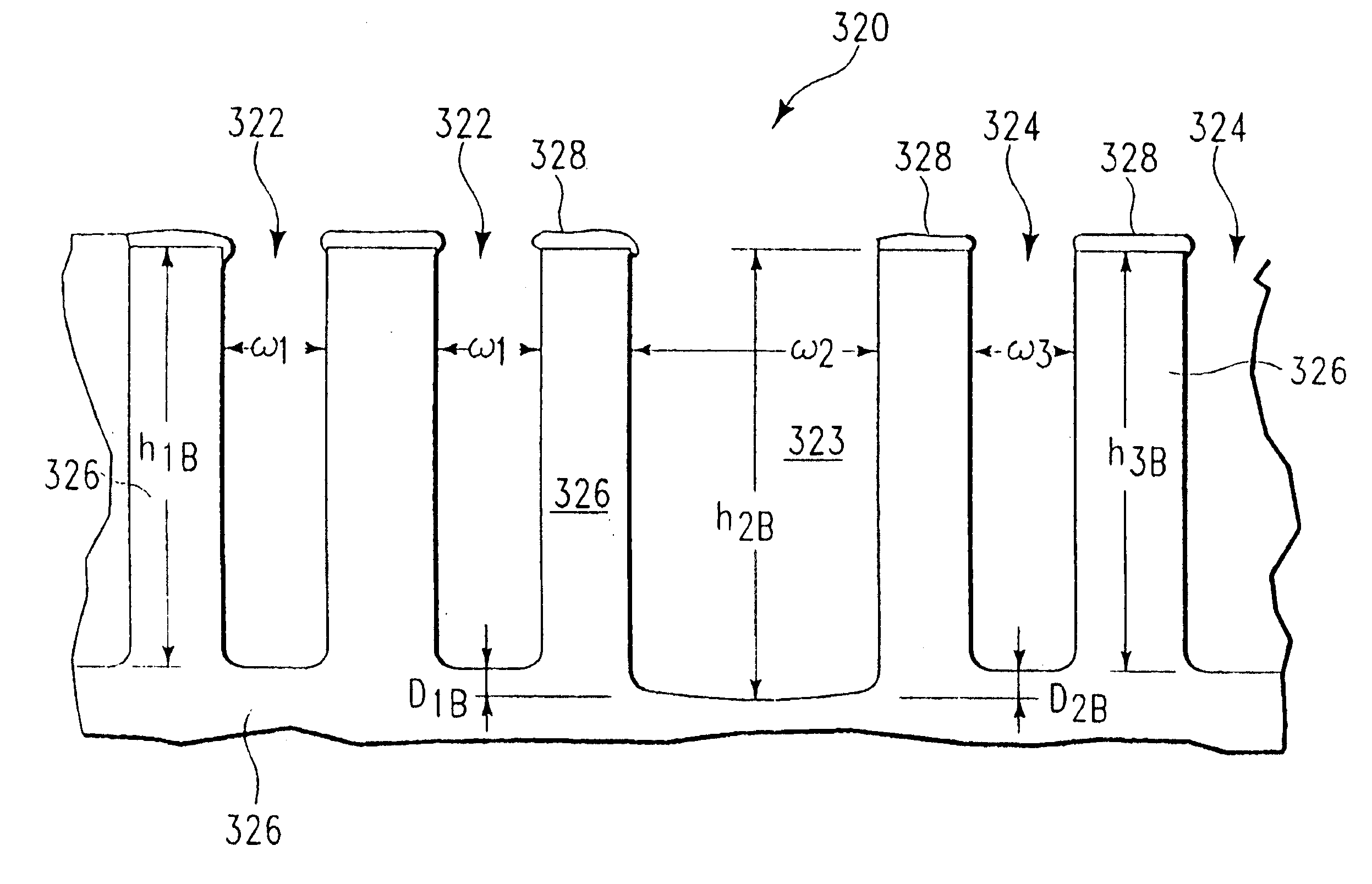
[0034]Data for one embodiment of the present invention, which makes use of a stabilizing etchant which is constantly present during the etch process, is presented in Table One as Run #4, the appearance of the etched sidewalls of the trench is shown in FIG. 2B, and the degree of microloading which occurred is shown in FIG. 3B. A patterned i-line photoresist mask was formed over a silicon substrate. In a first etch step, the exposed portion of the silicon substrate was contacted with a plasma generated from a stabilizing etchant gas in combination with a reactive etching gas. Subsequently, in a second step, the etched silicon surface was contacted with a plasma generated from the same stabilizing etchant gas, in combination with a polymer-forming gas. Steps one and two were repeated a number of times to provide deep etching into the silicon substrate.

[0035]With respect to FIG. 2B, the trench structure 220 includes a patterned i-line photoresist masking layer 222 and an underlying sili...


PUM


Abstract

We have developed an uncomplicated method of plasma etching deeply recessed features such as deep trenches, of at least 5 μm in depth, in a silicon-containing substrate, in a manner which generates smooth sidewalls, having a roughness of less than about 1 μm, typically less than about 500 nm, and even more typically between about 100 nm and 20 nm. Features having a sidewall taper angle, relative to an underlying substrate, typically ranges from about 85° to about 92° and exhibiting the smooth sidewalls are produced by the method. In one embodiment, a stabilizing etchant species is used constantly during the plasma etch process, while at least one other etchant species and at least one polymer depositing species are applied intermittently, typically periodically, relative to each other. In another embodiment, the stabilizing etchant species is used constantly and a mixture of the other etchant species and polymer depositing species is used intermittently.

Description

BACKGROUND OF THE INVENTION[0001]1. Field of the Invention[0002]The present invention pertains to a method of plasma etching recessed structures such as a deep trench in a substrate. The plasma source gas used to generate plasma etchant species is modulated during the etching process. The method is particularly useful in combination with particular plasma source gases for etching trenches in a silicon substrate.[0003]2. Brief Description of the Background Art[0004]Deep recessed structure etching is one of the principal technologies currently being used to fabricate microstructure devices, and is an enabling technology for many microelectromechanical systems (MEMS) applications. Strict control of the etch profile is required for these new, complex devices to perform satisfactorily. In a number of instances, it is desired to etch a vertical side wall, where vertical typically means that a taper angle formed by the side wall with a horizontal line drawn at the base of the side wall ran...

Claims


Application Information

Patent Timeline
Patent Type & Authority Patents(United States)
IPC IPC(8): H01L21/302H01L21/3065
CPCH01L21/30655
Inventor CHINN, JEFFREY D.RATTNER, MICHAELPORNSIN-SIRIRAK, NICHOLASLI, YANPING
Owner APPLIED MATERIALS INC
Why Eureka
Try Eureka