
Scanned beam image capture device with a plurality of scan regions

a technology of scanning beam and image capture, which is applied in the direction of sensing record carriers, instruments, sensing by electromagnetic radiation, etc., can solve the problems of large power consumption, large size of crts, and inconvenient portability and head-mounted applications,

Inactive Publication Date: 2006-07-11
MICROVISION
View PDF49 Cites 42 Cited by
  • Summary
  • Abstract
  • Description
  • Claims
  • Application Information

AI Technical Summary

Benefits of technology

[0013]Optical sources are aligned to provide the beams of light to the scanning mechanism from respective input angles. The input angles and orientations of the mirrors are selected such that the scanning mechanism sweeps the beams of light across respective distinct regions of an image field. Because the respective regions are substantially non-overlapping, each beam of light generates a substantially spatially distinct region of the image. The respective regions are immediately adjacent or may overlap slightly, so that the spatially distinct regions are “tiled” to form a contiguous image. Because movement of the mirrors can produce simultaneous movement of the beams, the display can produce each of the spatially separate regions simultaneously. The scan angle θ and the mirror dimensions in part determine the number of pixels drawn for each beam. The total number of pixels in a line can thus substantially equal the number of pixels for each beam multiplied by the number of beams.
[0020]In one embodiment of the alternate feeding approach, for each mirror a single light emitter feeds an input fiber that is selectively coupled to one of two separate fibers by an optical switch. During forward sweeps, the optical switch couples the input fiber to a first of the separate fibers so that the first separate fiber forms the first optical source. During reverse sweep, the optical switch feeds the second separate fiber so that the second separate fiber forms the second source. This embodiment thus allows a single light emitter to provide light for both optical sources.

Problems solved by technology

Such devices suffer from several limitations.
For example, CRTs are bulky and consume substantial amounts of power, making them undesirable for portable or head-mounted applications.
Such screens have limited use in head mounted applications or in applications where the display is intended to occupy only a small portion of a user's field of view.
Such displays have been reduced in size, at the cost of increasingly difficult processing and limited resolution or brightness.
Also, improving resolution of such displays typically requires a significant increase in complexity.
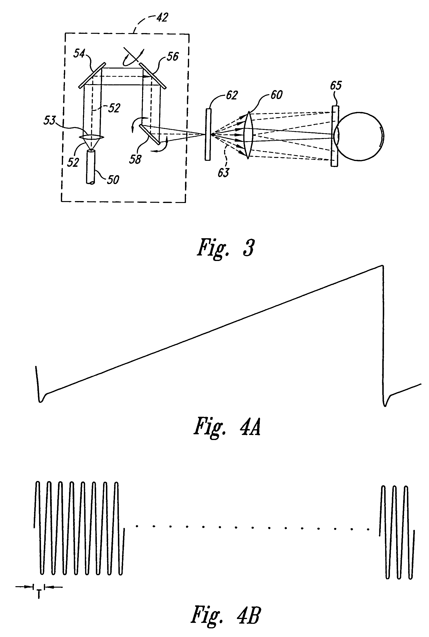
One difficulty that may arise with such displays is raster pinch, as will now be explained with reference to FIGS. 3–5.
This uneven spacing can cause the pixels to overlap or can leave a gap between adjacent rows of pixels.
Moreover, because the image information is typically provided as an array of data, where each location in the array corresponds to a respective position in the ideal raster pattern 69, the displaced pixel locations can cause image distortion.
Consequently, a large mirror and larger scan angle may produce unacceptable refresh rates.

Method used


Image

  • Scanned beam image capture device with a plurality of scan regions
  • Scanned beam image capture device with a plurality of scan regions
  • Scanned beam image capture device with a plurality of scan regions

Examples


Embodiment Construction

[0068]As shown in FIG. 6, a scanned beam display 70 according to one embodiment of the invention is positioned for viewing by a viewer's eye 72. While the display 70 is presented herein is scanning light into the eye 72, the structures and concepts described herein can also be applied to other types of displays, such as projection displays that include viewing screens.

[0069]The display 70 includes four principal portions, each of which will be described in greater detail below. First, control electronics 74 provide electrical signals that control operation of the display 70 in response to an image signal VIMfrom an image source 76, such as a computer, television receiver, videocassette player, DVD player, remote sensor, or similar device.

[0070]The second portion of the display 70 is a light source 78 that outputs modulated light beams 80, each having a modulation corresponding to information in the image signal VIM. The light source 78 may utilize coherent light emitters, such as la...


PUM


Abstract

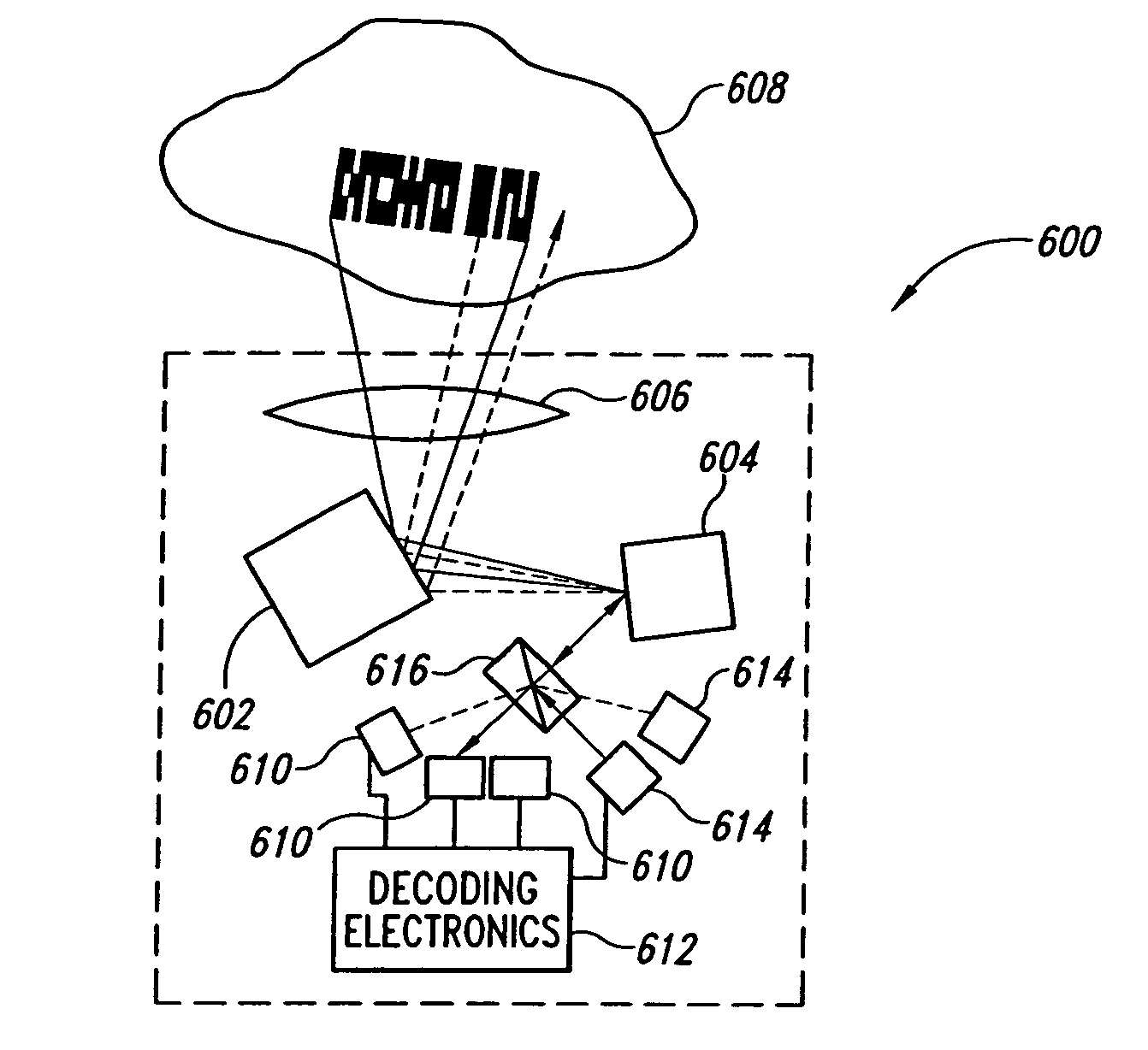
A display apparatus includes a scanning assembly that scans about two or more axes, typically in a raster pattern. A plurality of light sources emit light from spaced apart locations toward the scanning assembly such that the scanning assembly simultaneously scans more than one of the beams. The scanning assembly includes a plurality of mirrors that sweep their respective beams through respective regions of an image field. The regions are immediately adjacent so that an overall image is produced by “tiling” of the regions. Because sweeps of the scanning assembly scan a plurality of tiles simultaneously the resolution and / or field of view of a display for a given scan angle and mirror size is increased relative to a single mirror sweeping a single beam. In alternative embodiments, tiling is used for imaging. Also, various approaches to controlling the frequency responses of the various scanners are described, including active control of MEMs scanners and passive frequency tuning.

Description

[0001]This is a continuation of application Ser. No. 10 / 186,018, filed Jun. 29, 2002, now U.S. Pat. No. 6,762,867 which is a divisional of application Ser. No. 09 / 369,672, filed on Aug. 5, 1999 and issued as U.S. Pat. No. 6,433,907 on Aug. 13, 2002.TECHNICAL FIELD[0002]The present invention relates to scanned light devices and, more particularly, to scanned light beam displays and imaging devices for viewing or collecting images.BACKGROUND OF THE INVENTION[0003]A variety of techniques are available for providing visual displays of graphical or video images to a user. In many applications cathode ray tube type displays (CRTs), such as televisions and computer monitors produce images for viewing. Such devices suffer from several limitations. For example, CRTs are bulky and consume substantial amounts of power, making them undesirable for portable or head-mounted applications.[0004]Matrix addressable displays, such as liquid crystal displays and field emission displays, may be less bul...

Claims


Application Information

Patent Timeline
IPC IPC(8): G02B26/08
CPCG02B26/08
Inventor LIPPERT, THOMAS M.TEGREENE, CLARENCE T.
Owner MICROVISION
Learn More