Shift control apparatus for vehicle step-variable automatic transmission

a technology of automatic transmission and shift control, which is applied in the direction of instruments, transportation and packaging, gearing, etc., can solve the problems of high risk of deterioration of vehicle fuel economy, frequent shift-up and shift-down actions of automatic transmission, and vehicle operator's discomfort in uphill running, so as to improve the drivability of the vehicle

Inactive Publication Date: 2006-07-11
TOYOTA JIDOSHA KK
View PDF10 Cites 21 Cited by
  • Summary
  • Abstract
  • Description
  • Claims
  • Application Information

AI Technical Summary

Benefits of technology

[0007]The present invention was made in view of the background discussed above. It is therefore an object of the present invention to provide a shift control apparatus for a step-variable automatic transmission for a vehicle wherein the automatic transmission has a plurality of selectable groups of forward-drive positions having respective different sets of speed ratios, the shift control apparatus being arranged to suitably select one of the groups of forward-drive positions of the automatic transmission, which enables the vehicle to be driven with an adequate drive force with the automatic transmission placed in a relatively high-speed forward-drive position, for thereby restricting the frequent shifting actions of the automatic transmission and improving the drivability of the vehicle while reducing the deterioration of fuel economy of the vehicle.
[0011]The shift control apparatus of the present invention described above is arranged to control the shifting actions of an automatic transmission having a plurality of selectable groups of forward-drive positions each group including at least one high-speed position each having a speed ratio which is different from that of each high-speed position of any other of the selectable groups. In the present shift control apparatus, the drive-force-increase determining portion determines whether the vehicle drive force is required to be increased with the automatic transmission placed in one of the at least one high-speed position, and when this drive-force-increase determining portion has determined that the vehicle drive force is required to be increased, the drive-position-group selecting portion selects one of the selectable groups, which one group include the at least one high-speed position each having the speed ratio higher than that of each high-speed position of any other of the selectable groups. Accordingly, the vehicle can be driven with a sufficient drive force and a high degree of accelerating and decelerating drivability, while preventing or restricting frequent shifting actions of the automatic transmission and improving the fuel economy of the vehicle.
[0021]In the shift control apparatus according to the fifth preferred form of the invention, the drive-force-increase determining portion determines that it is necessary to increase the vehicle drive force, when the tracing control determining portion 110 (S2) has determined that the vehicle is under the tracing control so as to trace the preceding vehicle. Accordingly, the vehicle can be driven with an adequate drive force and with a high degree of vehicle accelerating and decelerating drivability, so as to trace the preceding vehicle, while preventing or restricting frequent shift-up and shift-down actions of the transmission. In the conventional tracing control, the vehicle is repeatedly and alternately accelerated and decelerated with alternate shift-down and shift-up actions of the automatic transmission, so as to maintain a predetermined distance between the vehicle in question and the preceding vehicle. In the present shift control apparatus, however, the drive-position-group selecting portion selects one of the selectable groups of forward-drive positions which provides a larger drive force, thereby preventing the frequent shifting actions of the automatic transmission, which would take place during the tracing control of the vehicle.
[0023]The shift control apparatus according to the sixth preferred form of the invention permits the vehicle to be driven with a sufficient drive force and a high degree of vehicle accelerating and decelerating drivability, while preventing or restricting frequent shifting actions of the transmission, even when the vehicle is under the tracing control wherein the vehicle speed is controlled such that the distance between the vehicle in question and the preceding vehicle, which is detected by the vehicle-to-vehicle distance sensor provided on the vehicle, is maintained at a predetermined value.

Problems solved by technology

The frequent shift-up and shift-down actions of the automatic transmission are felt uncomfortable by the vehicle operator.
Since the fifth-speed and fourth-speed positions have a considerably large difference in the speed ratio, the use of the fourth-speed position in place of the fifth-speed position during the uphill running of the vehicle is also felt uncomfortable by the vehicle operator in respect of the vehicle acceleration and deceleration characteristics.
Further, the restriction of the shift-up action of the automatic transmission to the highest-speed position has a high risk of deterioration of the fuel economy of the vehicle.

Method used


Image

  • Shift control apparatus for vehicle step-variable automatic transmission
  • Shift control apparatus for vehicle step-variable automatic transmission
  • Shift control apparatus for vehicle step-variable automatic transmission

Examples


first embodiment

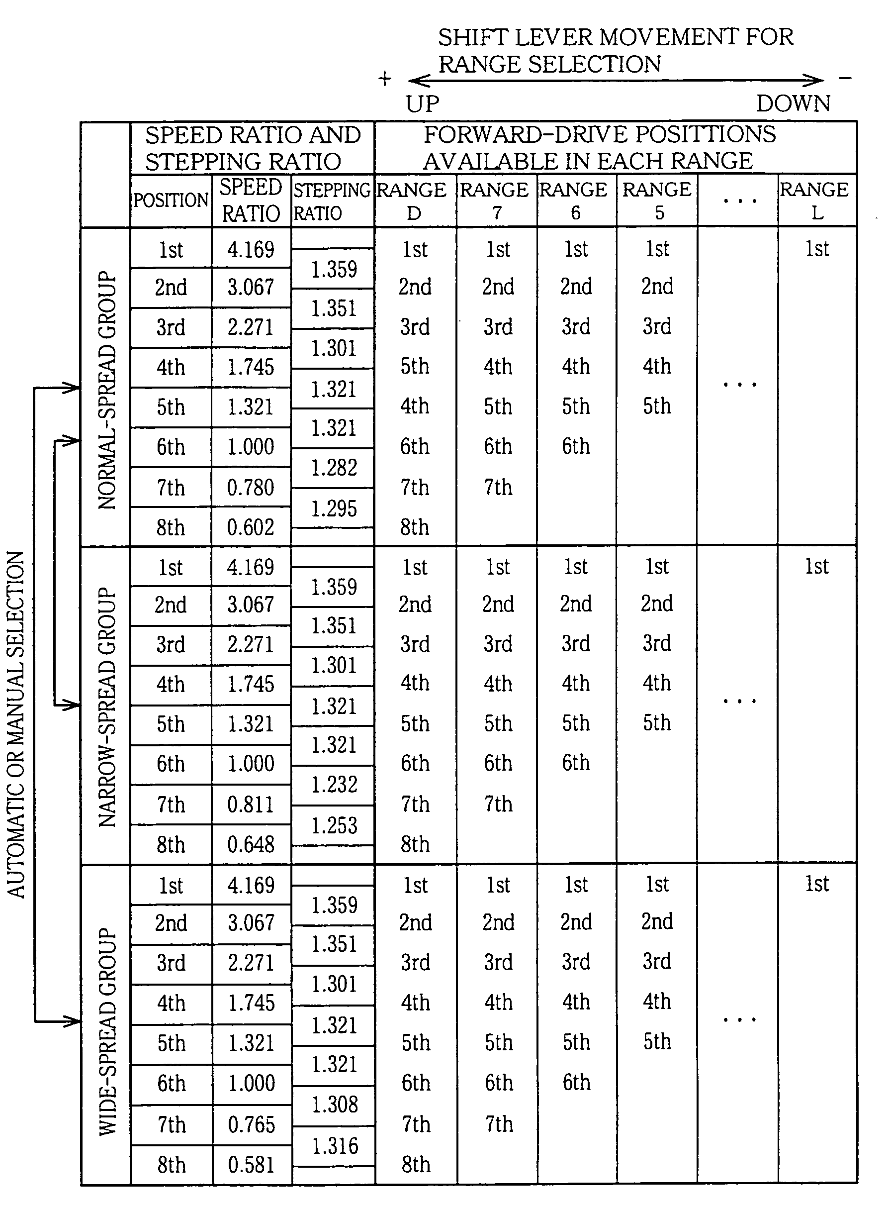
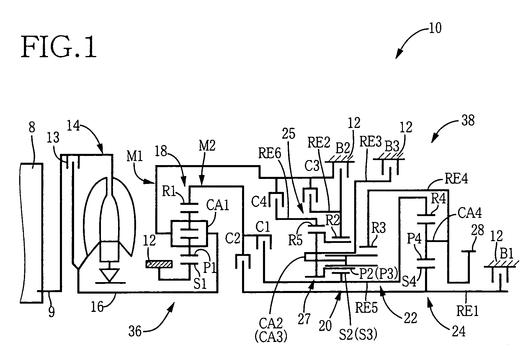
[0049]Referring to first to the schematic view of FIG. 1, there is illustrated a basic arrangement of a step-variable automatic transmission in the form of a planetary gear type multiple-step automatic transmission 10 for a motor vehicle, which is constructed according to this invention. The automatic transmission 10 (hereinafter referred to simply as “transmission 10”) has a plurality of operating positions which are selectively established, so that the speed ratio of the transmission 10 is changeable in steps. As shown in FIG. 1, the transmission 10 includes a fluid-operated power transmitting device in the form of a torque converter 14 with a lock-up clutch 13 incorporated therein, an input shaft 16 connected to the torque converter 14, a first shifting portion 36, a second shifting portion 38, and an output gear 28, which are disposed coaxially with each other, within a transmission casing 12 attached to the body of the vehicle. The first shifting portion 36 is constituted princ...

third embodiment

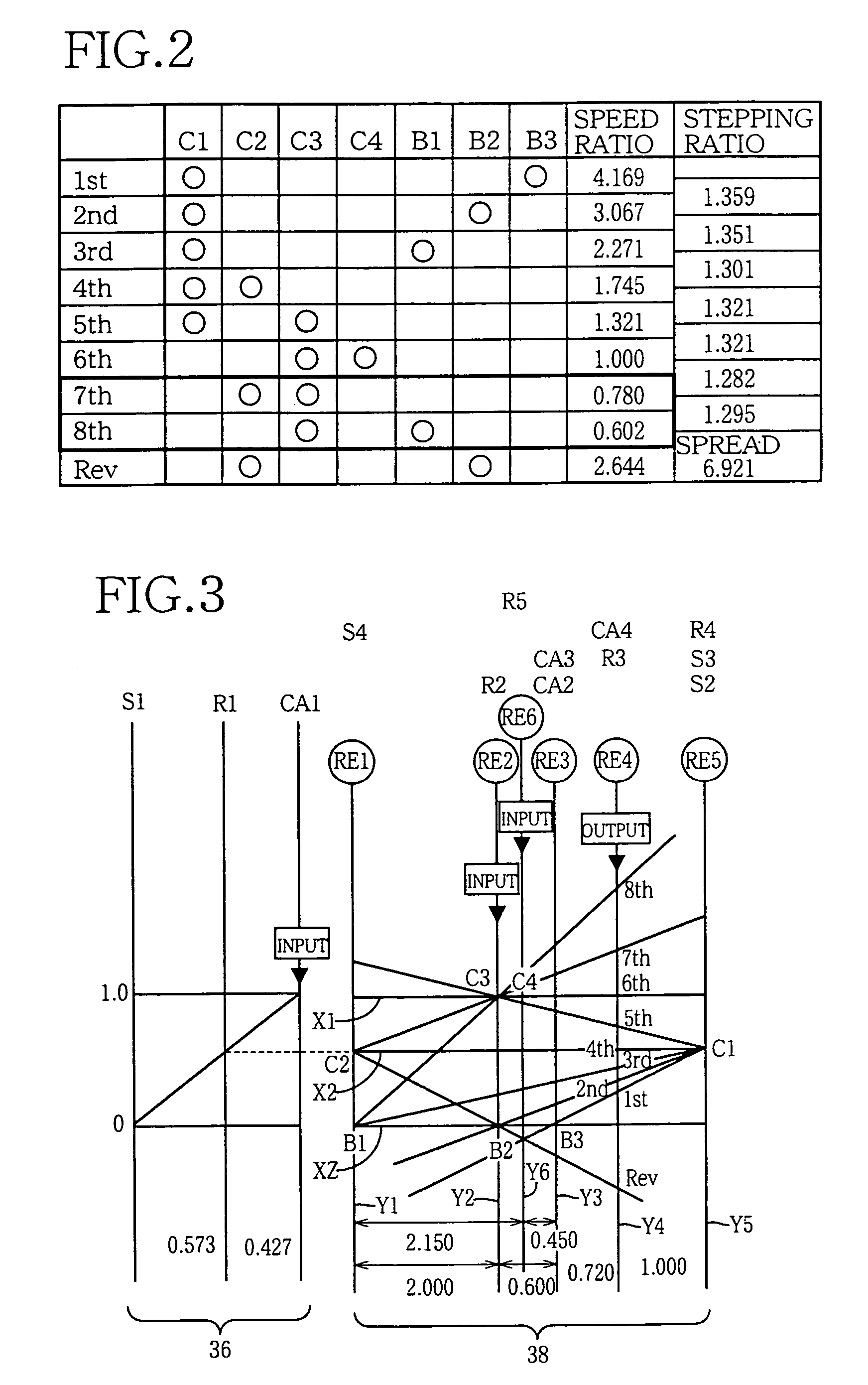
[0099]As shown in the schematic view of FIG. 17, an automatic transmission 60 includes a first shifting portion 66 having the first and second planetary gear sets 18, 20, and a second shifting portion 68 having the third and fourth planetary gear sets 22, 24. The transmission 60 has a first normal-spread group of ten operating positions indicated in the table of FIG. 18 and the collinear chart of FIG. 19.

[0100]Each of the first and second planetary gear sets 18, 20 of the first shifting portion 66 of the transmission 60 is of a single-pinion type. The first planetary gear set has a first sun gear S1, a first planetary gear P1, a first carrier P1 supporting the first planetary gear P1 such that the first planetary gear P1 is rotatable about its axis and rotatable about the axis of the first sun gear S1, and a first ring gear R1 meshing with the first sun gear S1 through the first planetary gear P1. The first planetary gear set 18 has a gear ratio ρ1 of about 0.429. The second planet...

fifth embodiment

[0101]In the first shifting portion 66, the first ring gear R1 and second sun gear S2 which are integrally connected to each other are selectively fixed by a first brake B1 to the non-rotatable member in the form of the transmission casing 12, and the first carrier CA1 is selectively fixed by a second brake B2 to the transmission casing 12, while the second carrier CA2 functions as the second intermediate output member connected to the second intermediate output path M2. The first sun gear S1 and second ring gear R2, which are integrally connected to each other, are function as the first intermediate output member connected, and are connected to the input shaft 16 and the first intermediate output path M1. The first shifting portion 66 is arranged to transmit a rotary motion of the input shaft 16 to the second shifting portion 68 through the first intermediate output path M1, and the second intermediate output path M2 the speed of which is reduced with respect to that of the first i...


PUM


Abstract

A shift control apparatus for controlling shifting actions of a step-variable automatic transmission for a vehicle, which has a plurality of selectable groups of forward-drive positions having respective different sets of speed ratios, each one of the selectable groups of forward-drive positions including at least one high-speed position each having a speed ratio which is different from that of each high-speed position of any other of the selectable groups, the shift control apparatus including a drive-force-increase determining portion operable to determine whether it is necessary to increase a drive force of the vehicle with the automatic transmission placed in any high-speed position, and a drive-position-group selecting portion operable to select one of the selectable groups of forward-drive positions which includes the at least one high-speed position each having the speed ratio higher than that of each high-speed position of any other of the selectable groups, when the drive-force-increase determining portion has determined that it is necessary to increase the drive force of the vehicle with the automatic transmission placed in any high-speed position.

Description

[0001]This application is based on Japanese Patent Application No. 2003-346269 filed Oct. 3, 2003, the contents of which are incorporated hereinto by reference.BACKGROUND OF THE INVENTION[0002]1. Field of the Invention[0003]The present invention relates in general to a shift control apparatus for a vehicle step-variable automatic transmission having a plurality of selectable groups of forward-drive positions having respective different sets of speed ratios, and more particularly to techniques associated with the shift control apparatus, for improving the drivability of a vehicle by suitably selecting one of the groups of forward-drive positions of the automatic transmission, which enables the vehicle to be driven with an adequate drive force with the automatic transmission placed in a relatively high-speed forward-drive position.[0004]2. Discussion of Related Art[0005]A known shift control apparatus for a vehicle step-variable automatic transmission tends to suffer from frequent alt...

Claims


Application Information

Patent Timeline
Patent Type & Authority Patents(United States)
IPC IPC(8): B60K17/06F16H59/66F16H3/66F16H3/62F16H59/00F16H59/14F16H59/52F16H61/02F16H61/10F16H61/686F16H61/70G06F7/00
CPCF16H3/663F16H59/66F16H61/0213F16H61/70F16H3/666Y10T477/60F16H59/52F16H61/10F16H61/686F16H2059/142F16H2061/6642F16H2200/006F16H2200/0086F16H2200/201F16H2200/2023F16H2200/2025F16H2200/2048F16H2059/663F16H2059/084
Inventor OTA, HIROFUMIHONDA, ATSUSHIABE, AKIHARUTABATA, ATSUSHI
Owner TOYOTA JIDOSHA KK
Why Eureka
Try Eureka