
Failure information management method and management server in a network equipped with a storage device

a technology of failure information management and management server, which is applied in the field of computer systems, can solve the problems of increasing management costs and time-consuming response to failures, and achieve the effect of increasing management costs and a greater degree of freedom

Inactive Publication Date: 2006-07-11
HITACHI LTD
View PDF50 Cites 42 Cited by
  • Summary
  • Abstract
  • Description
  • Claims
  • Application Information

AI Technical Summary

Benefits of technology

[0012]With the failure monitoring function of the SAN manager, the SAN administrator identifies the device and component that is causing a failure based on events issued from multiple devices. This will be referred to hereinafter as “failure investigation”. By having the virtualization device provide virtual volumes, a greater degree of freedom is possible for the configuration of volumes provided to the server. However, investigating a failure based on failure messages (SNMP Traps and the like) issued by devices from multiple vendors connected to the SAN depends on the SAN administrator having a high degree of knowledge about individual devices. This increases management costs.
[0015]A second object of the present invention is to allow the SAN administrator and high-level system management software to receive, out of the failure messages issued by the devices connected to the SAN, the failure information that is necessary.

Problems solved by technology

This increases management costs.
However, since the definition of the severity of a failure is dependent on the individual devices connected to the SAN, for each failure, the SAN administrator must judge whether a particular event from a particular device has a high severity.
Thus, responding to a failure becomes time consuming.

Method used


Image

  • Failure information management method and management server in a network equipped with a storage device
  • Failure information management method and management server in a network equipped with a storage device
  • Failure information management method and management server in a network equipped with a storage device

Examples


Embodiment Construction

[0045]Various embodiments of the present invention will be described below, with reference to the drawings; however, the present invention is not restricted to these embodiments.

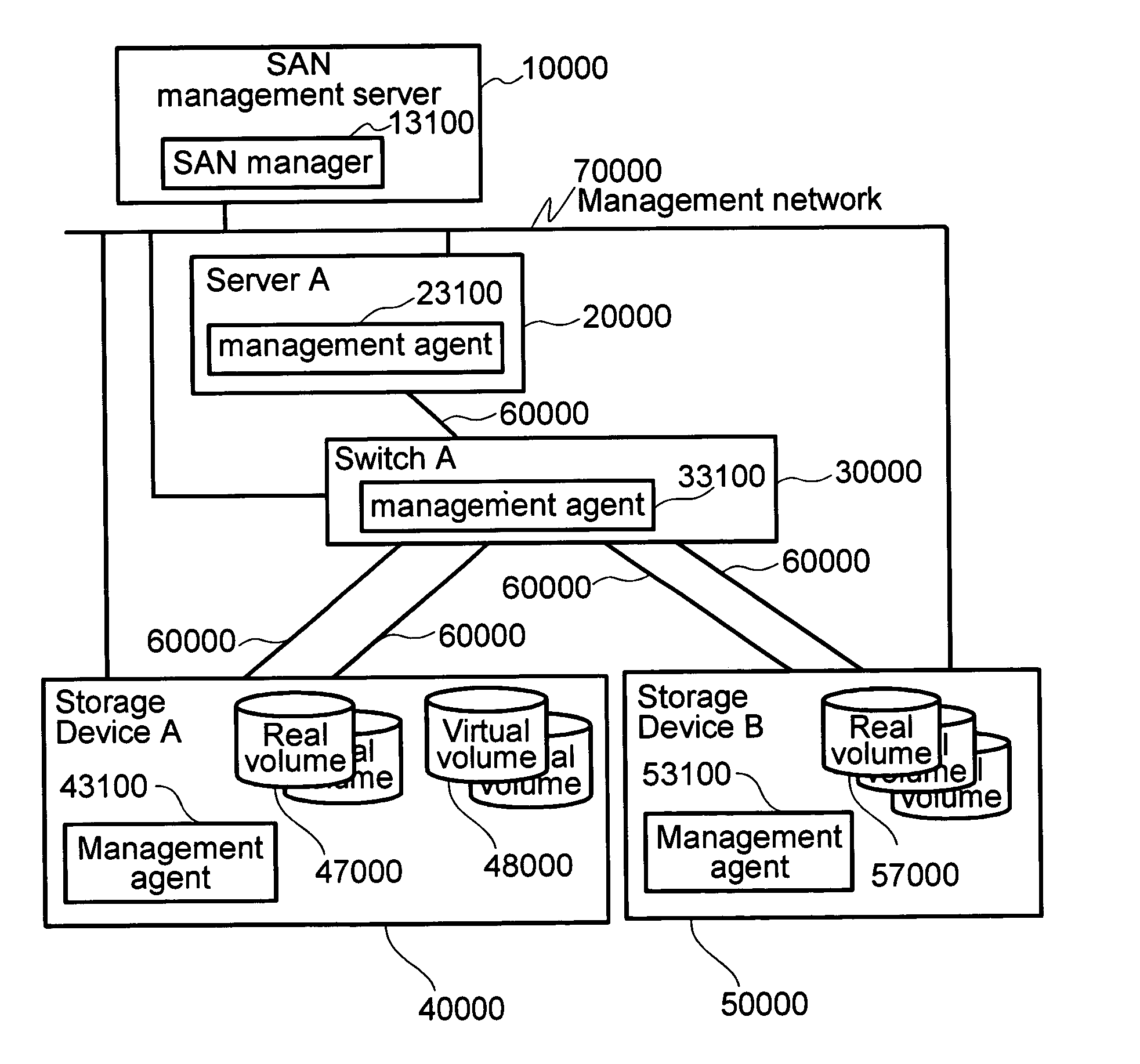
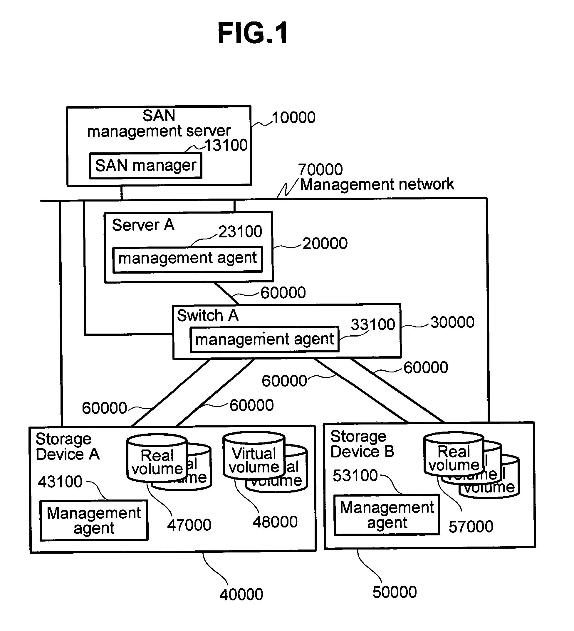
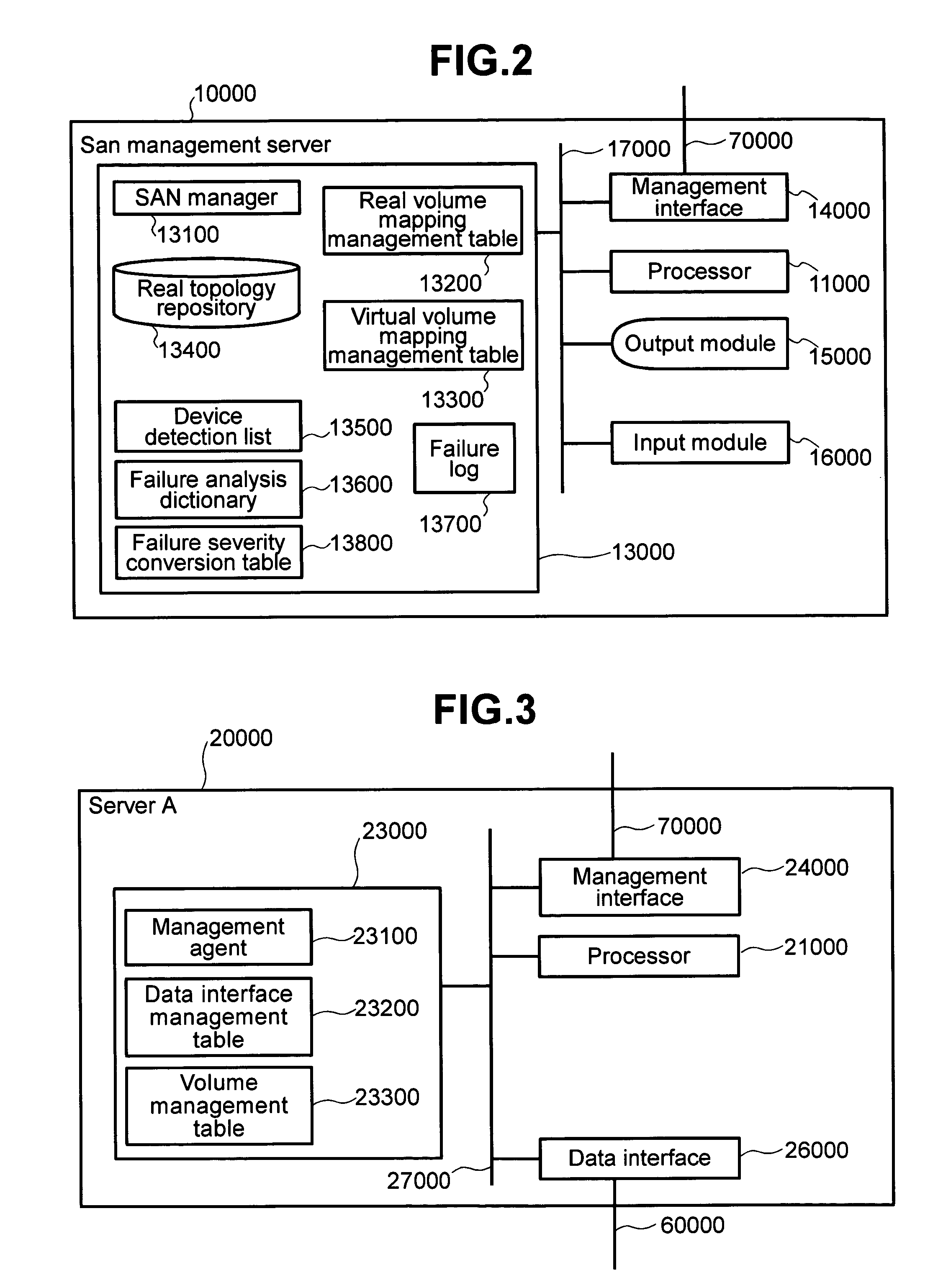
[0046]First, an example of the SAN architecture according to this embodiment will be described. FIG. 1 through FIG. 6 show an example of a SAN and devices connected to the SAN. FIG. 9 through FIG. 18 show management information contained in the devices.

[0047]FIG. 1 shows an example of SAN architecture. The SAN of the present invention includes: at least one server having a management agent; at least one switch having a management agent; at least one virtualization device having a management agent; at least one storage device having a management agent; and a single SAN management server having a SAN manager.

[0048]For convenience in the following description, the SAN of this embodiment includes: a single server (server A) 20000, a single switch (switch A) 30000, a single storage device with virtual volume tech...


PUM


Abstract

Failure investigation in a SAN providing virtual volumes requires a high degree of knowledge from the SAN administrator, who also evaluates the relative severities of failure events from different devices. The SAN manager obtains information from management agents in the devices. Using this information, the SAN manager manages the association between the server and the virtual volumes and the real volumes. The SAN manager receives failure messages from multiple devices and uses the association and a failure analysis dictionary table to determine the contents of the failure messages and associations between failure messages. Failures that are causal failure are displayed. The SAN manager is equipped with a conversion table for converting failure messages issued from different storage devices to a common severity. When a failure message is received, a notification is sent to a high-level program and to an administrator based on the common severity defined in the conversion table.

Description

BACKGROUND OF THE INVENTION[0001]The present invention relates to a computer system that is equipped with a storage system. More specifically, the present invention relates to a method and device for managing storage system failures in storage area networks (Storage Area Network, hereinafter referred to as a SAN) in which real volumes from a storage system are provided by a server as virtual volumes.(1) SANs[0002]In recent years, the use of SANs has become more widespread. A SAN is a network dedicated to data storage in which the storage is consolidated and separated from servers in the system. The deployment of SANs makes it possible to provide high-speed data transfer, high scalability and availability in a storage system, as well as efficient usage of storage resources.(2) SAN Management[0003]The high scalability of SAN-based storage systems allows devices (servers, switches, storage devices) from multiple vendors to be mixed in a SAN. Using a SAN without disruption requires SAN ...

Claims


Application Information

Patent Timeline
Patent Type & Authority Patents(United States)
IPC IPC(8): G06F11/00G06F13/10G06F3/06G06F11/07G06F12/00H02H3/05H04L12/24H04L12/26
CPCG06F11/0727G06F11/0781G06F11/079H04L41/065H04L41/0213H04L41/22H04L41/08H04L41/12H04L41/046H04L41/40
Inventor YAMAMOTO, MASAYUKI
Owner HITACHI LTD
Learn More